hello guys one question how you guys call the circuit from the positive rail to the negative rail ?
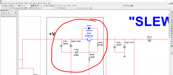
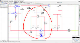
This is a capacitance multiplier.
The value of 470uF at the base is multiplied by the current gain (beta) of the transistor.
Those are 'Capacitance Multipliers', a simple active filter to help remove ripple and noise from the power supply lines feeding the low current sections.
This is a capacitance multiplier.
The value of 470uF at the base is multiplied by the current gain (beta) of the transistor.
thanks so in Spanish that will be like " capacitancia multiplicada " close enough 😛 I just need to know to explain my friends 🙂
thanks so in Spanish that will be like " capacitancia multiplicada " close enough 😛 I just need to know to explain my friends 🙂
Exactamente 😉
I see I am learning Spanish now.
But does learning include remembering?
"Multiplicada" sounds like a sequence in Argentinian Tango.
I'll need to ask my teacher.
But does learning include remembering?
"Multiplicada" sounds like a sequence in Argentinian Tango.
I'll need to ask my teacher.
Hi Rhythmsandy,
It looks very much like a local oscillation.
I don't want to "promote" my designs here in Pete's thread - just see the OPS schematic here:
VHex variation
Note D14, C10, C11, R25, R26. Red LED in the spreader makes the tempco of the spreader very close to the one of IRFP devices. You don't need to place the LED on the main heatsink (Q10 must be there, as usual).
This output stage will work with Kypton V perfectly.
Cheers,
Valery
P.S. Do you have an oscilloscope connected to the output?
Thanks valery i have changed the compensation caps from 100pf to 33pf and also the Source resistors to 0.33ohm and all seems working stable.
The only concern in my circuit is the bias pot is too sensitive please suggest me what values to choose to make the bias go considerably smooth like from 300ohm pot position to 100ohm the bias could increase from 0ma to 1A. Right now im getting like for just 5 ohm difference the bias will be from 0ma to 500ma which is little bit of variation its crawling up way too fast.
Sound wise: At 120ma per hexfet I sound is quite fast but not as neutral as a transistor varient. Bass grip is pretty good. Somehow the neutrality which was found in either Lateral mosfets and Bipolars is not there.
I tried the same IPS + VAS for both Bipolar and Laterals earlier.
I wanted to know to build
a 200W into 8ohm and 350W in 4ohm amp at 70V how many hexfet pairs are recommended for safe operation mostly for highend Home Theater application.
a 100W into 8ohm and 180W in 4ohm amp at 55V how many hexfet pairs
That much drastic change in bias current is usually a sign the amplifier is going into oscillation.
Exactly - Rhythmsandy, if you use the spreader with the values, close to the ones at my link, having sensitivity that high - your amplifier oscillates.
Oscillation may or may not kill the output stage, but in any case it negatively influences the sound at highs. Unless you solve the oscillation issue, it will not sound as expected.
Oscillation may or may not kill the output stage, but in any case it negatively influences the sound at highs. Unless you solve the oscillation issue, it will not sound as expected.
I am inlined to agree.That much drastic change in bias current is usually a sign the amplifier is going into oscillation.
Check with an analogue oscilloscope
Exactly - Rhythmsandy, if you use the spreader with the values, close to the ones at my link, having sensitivity that high - your amplifier oscillates.
Oscillation may or may not kill the output stage, but in any case it negatively influences the sound at highs. Unless you solve the oscillation issue, it will not sound as expected.
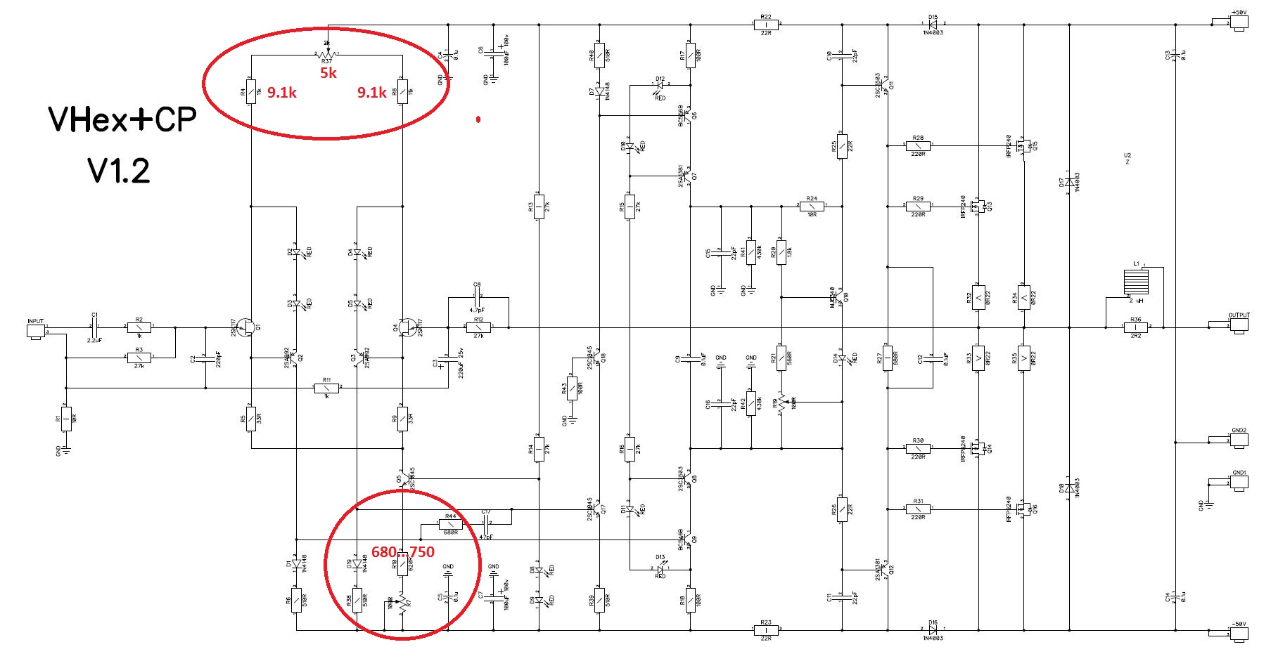
you mean to say the one in this link?
http://www.diyaudio.com/forums/atta...0855673-sons-vhex-00-vhex-cp-sch-1.2-test.jpg
Yes.
In the attached pic.
R55 is the bias controlling resistor so now i see considerable improvement in the range at 580 the bias is about 1.9ma per mosfet and for 500 its 108ma per mosfet which is quite sufficient.
Now do C7 C14 R38 and R40 responsible to stop the oscillation?
Attachments
Now do C7 C14 R38 and R40 responsible to stop the oscillation?
Yes, but they strongly depend on particular front-end topology and compensation scheme.
If they are not specified in Kypton V2 - you don't need them.
Last edited:
ok how about the 4148 and 12V zener diodes at the output stage which its said will stop the overshoot in current in the load which generally occur rarely.
Secondly i read once in pass group that mosfets are better to drive the mosfet OPS. In that case since toshiba mosfets are obsolete can we use Fairchild FQP3N30?
I think what I found out using 1381 3503 as drivers is that they cannot take much dissipation or its definitely my choice of having low cob transistors. But like nelson pass choice especially in driving hexfets to use mosfets. What do you say about this?
I feel it does makes sense to me i feel it will reduce distortion to an extent since mosfets are quite fast and smaller ones are even faster so switchoff times are definitely low hence quick turnoff of the mosfets than transistors.
Im currently mounting the Vbe multipliier onthe driver heatsink which is another smaller heatsink where the Vas OPS 1381 3503 and 2sc5171 1930 are mounted. I did once like this for the lateral mosfets and it worked then but now do i need to move the Vbe multiplier near to the OPS? On the same heatsink as OPS?
ok how about the 4148 and 12V zener diodes at the output stage which its said will stop the overshoot in current in the load which generally occur rarely.
Secondly i read once in pass group that mosfets are better to drive the mosfet OPS. In that case since toshiba mosfets are obsolete can we use Fairchild FQP3N30?
I think what I found out using 1381 3503 as drivers is that they cannot take much dissipation or its definitely my choice of having low cob transistors. But like nelson pass choice especially in driving hexfets to use mosfets. What do you say about this?
I feel it does makes sense to me i feel it will reduce distortion to an extent since mosfets are quite fast and smaller ones are even faster so switchoff times are definitely low hence quick turnoff of the mosfets than transistors.
But you will be wasting some additional rail voltage to the mosfet drivers..
but now as valery said i have made changes and even at 60ma per mosfet at 10KHz the THD is about 0.0057% which is quite ashtonishing so why its said to increase bias for the Hexfet to attain linearity?
Vbe multiplier must be mounted on the main heatsink, where the output transistors are mounted. Its tempco is particularly tuned for IRFP240/9240 HexFETS.
Lateral MOSFETs - completely different story in terms of thermal characteristics.
MOSFET drivers - possible, but it may require additional compensation. It doesn't make sense to change some drivers in the well-tested design to some other ones just because you have read that MOSFET ones are good, even from such a trusted person as Nelson Pass. This kind of change always requires additional engineering, especially considering stability matters.
1381 3503 don't have to dissipate much power in case they drive MOSFETs - gate currents are low, so the quiescent current for the driver stage is set as moderate, enough for driving the MOSFETs' gate capacitance. If the output transistors would be BJTs - a very different story, their base currents vary, reaching high levels at high output power.
So... better don't make changes unless you are going to perform things like feedback loop AC analysis.
- Home
- Amplifiers
- Solid State
- Slewmaster - CFA vs. VFA "Rumble"