Borys,
Nice work on that design. I like how compact it is and if the input section was incorporated it would be a very small package indeed.
Nice work on that design. I like how compact it is and if the input section was incorporated it would be a very small package indeed.
I can't see the voltage divider and the way this is connected to laptopthimios
Yes the load is connected, the graph in STEPS looks linear but at higher F the distortions are rising up a bit. At the higher amplitude THD is rising too, but amp sounds really OK.
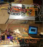
I am doing STEPS graphs to see if the amp has the same harmonics spectrum threw all audio band. Take a look at my setup bellow (you can see the ''linear'' graph on the laptop and 8R resistor and the clamp meter).
Sometimes thd graph is showing some design problems. For me THD figure does not mater much but I like to test it anyway to confirm that all is ok.
BTW
I will make double layer OPS prototype just for my learning process, heavy current track are as close together as possible. The PCB can be cut to make more room for the OP tranies.
regards
thimios
Bellow is my clean and tidy setup 😀 (please do not coment it, I know how it looks like)
The gnd return is connected to the clean ground. I am using same (I think) gnd layout as apex, the main star gnd is in the psu (the heavy current returns are spreaded, it looks like there are two star points at the pcb board). I am using 1k/47k divider, the return from it goes threw signal cable to the pcb board and than to the psu unit.
Sorry but I can not describe it better.
BTW
I have made small current adjustment adn speeded up a bit the Cliffjumper (up to approx 70V/us), the high freq performance have improved a bit. Bellow compared two versions (few resistor values changed only).
Attachments

Component selection help
Dear builders,
I’m almost ready to build the 5 pair OPS (Toshiba 2SC5200/2SA1943 output devices) with Spooky IPS. I have the boards and most of the components.
Still I have a few questions to more experienced builders about component selection I need to do.
OPS:
* 0,02uF/100V for PSU decoupling - I’m unable to find X7R capacitors rated for 100V at reasonable price (+shipping). Is it possible to use MKS or MKT types without any problems?
* 0,22 Ohm 5W emiter resistors - I saw that most of the builders used wirewound ceramic housing resistors. Is there any advantage using non-inductive MPC71 types even if the price is much higher and the pads are not exactly aligned to the PCB? Or is it absolutely OK to use the wirewounds?
* Drivers - if I’m using Toshiba 2SC5200/2SA1943 as output, is it OK to use them as drivers as well?
Spooky IPS:
* The input capacitor - I understand that this is an important part and I have to use MKP type. I can’t find any rated for 100V. Is it important to rate the input cap for 100V, or could be less?
* The same question about two 2,2uF capacitors in servo circuit (C11, C12 in Spooky). What is the voltage rating for these?
* Transistors - first I was unable to find the KSC1845, KSC1815, KSA1015, KSA992 devices, then I found that 2SA* and 2SC* are the equivalents for them and those are more available here. Anyway, I still couldn’t find KSA1381 and KSC3503 (Q12, Q13). Are there any substitutes which can be used without sound degradation? MJE340/350 perhaps?
Regarding PSU: I have 2 transformers 2x55V 500VA each, 25A bridge rectifiers and 24pcs 6800uF/100V capacitors. What is the recommended reasonable PSU filter capacity per rail? With those capacitors I can have 6x6800=40 800uF per rail. Should I use all or is it overkill?
Thanks for help.
Stefan
UniSlewMaster
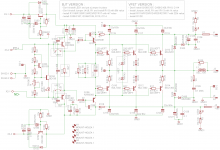
I had in mind to give a try at both BJT and VFET OPS so i decide to root a "universal board" with all option that allow to swap from FVET to BJT by just install or not install parts/jumper. Instruction are summerized on Schematic. With this Uni version one bath of 5 board from pcbCompagny allow to built both Ops with one spare board (min 5 board order)
Marc
Attachments

Good work!I had in mind to give a try at both BJT and VFET OPS so i decide to root a "universal board" with all option that allow to swap from FVET to BJT by just install or not install parts/jumper. Instruction are summerized on Schematic. With this Uni version one bath of 5 board from pcbCompagny allow to built both Ops with one spare board (min 5 board order)
Marc
I had in mind to give a try at both BJT and VFET OPS so i decide to root a "universal board" with all option that allow to swap from FVET to BJT by just install or not install parts/jumper. Instruction are summerized on Schematic. With this Uni version one bath of 5 board from pcbCompagny allow to built both Ops with one spare board (min 5 board order)
Marc
Very nice! Do you plan to post the gerbers for others to build from?
Very nice! Do you plan to post the gerbers for others to build from?
Yes for sure. If some people can take a look at the two pictures for checking...I have to let a little time appart because spend to much time on and don't seen anything...
I had in mind to give a try at both BJT and VFET OPS so i decide to root a "universal board" with all option that allow to swap from FVET to BJT by just install or not install parts/jumper. Instruction are summerized on Schematic. With this Uni version one bath of 5 board from pcbCompagny allow to built both Ops with one spare board (min 5 board order)
Marc
It would be a good idea to spread your output devices apart farther. The temperature and bias current runs higher on the center devices when they are that close together. OS has noticed this too.
Irfp slewmaster with single sided board
Hallo all,
Did someone perhaps build a 3-5 pair irfp output slewmaster with a single sided board and is willing to share ? 🙂
Hallo all,
Did someone perhaps build a 3-5 pair irfp output slewmaster with a single sided board and is willing to share ? 🙂
Marc,
If you go the effort to spread apart the output devices perhaps it would make sense to space them far apart enough to accommodate MT-200 devices.
If you go the effort to spread apart the output devices perhaps it would make sense to space them far apart enough to accommodate MT-200 devices.
It would be a good idea to spread your output devices apart farther. The temperature and bias current runs higher on the center devices when they are that close together. OS has noticed this too.
Yes Jason i read OS on that. I will take a look on how to but don't want to grown to much the board. The goal is to keep OPS and IPS on on a 300x120mm heatsink face. I don't remember if in OS case he has 3 or 5 output pair...
Marc,
If you go the effort to spread apart the output devices perhaps it would make sense to space them far apart enough to accommodate MT-200 devices.
To allow MT-200 it needs a lot of space for 3 pair. I could try if there is an interest but for my use the board will be to big.
Marc
It would be a good idea to spread your output devices apart farther. The temperature and bias current runs higher on the center devices when they are that close together. OS has noticed this too.
Here modification board take 1cm more in lentgh so OPS have 5mm more between them. On picture OPS package is TO264.
Marc
There's a couple other design upgrades that might be worth looking into.
Q104 might benefit from being mounted closer to one of the output devices so it can get a faster response to output device temperature changes.
Power rail feeds come through the fuses, feed to the two big reservoir caps, then the current reverses down the same trace to the output devices creating a very current area on the trace. Randy Slone recommended having a distinct current in and out path to eliminate this. The same issue is there with the output device decoupling caps.
I like the TO220 RE resistors. They save a lot of board space.
There's a couple other design upgrades that might be worth looking into.
Q104 might benefit from being mounted closer to one of the output devices so it can get a faster response to output device temperature changes.
Power rail feeds come through the fuses, feed to the two big reservoir caps, then the current reverses down the same trace to the output devices creating a very current area on the trace. Randy Slone recommended having a distinct current in and out path to eliminate this. The same issue is there with the output device decoupling caps.
I like the TO220 RE resistors. They save a lot of board space.
Yes i saw all these upgrade ans will try but some are quite complicated to apply, but i will take a try. For RE i like to use MCP71 that are really compact too.
Marc
For RE i like to use MCP71 that are really compact too.Yes i saw all these upgrade ans will try but some are quite complicated to apply, but i will take a try. For RE i like to use MCP71 that are really compact too.
Marc
And match cheaper from TO220.
TO220 resistors are getting to be all that is available for radial leads in North America.
On my sub amp I ran the power rails between the output devices to make it easier to hook the caps up. I put the fuses at the supply too. The first output device could be right at the end of the board that way.
It's always easier to look at the board after and see a bunch of things you should have done though. I put Q104 out in the middle of nowhere too. I didn't leave enough space for capacitors in the input section on mine.😡
For Q104 one way to go is to screwit right on a output device and connect it with wire. I've done that on my NBIP drom Quasi

For Q104 one way to go is to screwit right on a output device and connect it with wire. I've done that on my NBIP drom Quasi
That's always an option but there's more of a chance of lead breakage that way. OS mentioned it was possibly a source of oscillation when I was having problems a while back.
I see you used the vertical design for your output inductor. I like the look of them but mine always end up getting bent. The wood filler is a good idea while working on the amp. I might try that in the future.
- Home
- Amplifiers
- Solid State
- SlewMaster Builds