Thanks JW, and I know you didn't mean to write 10mm that would be one narrow board!
Yes, that's 100mm
Ha, Jason named them "cheapskate" in my honor. 😀
All of his IPS boards were 3"x4". 4"=10.16cm. I asked him to shrink them by 1.6mm so they would qualify for the "proto-type" discount which has a 10cm x 10cm limit. He was kind enough to reduce them for me and dubbed them "Cheapskate" layout to distinguish them from the originals.
All of his IPS boards were 3"x4". 4"=10.16cm. I asked him to shrink them by 1.6mm so they would qualify for the "proto-type" discount which has a 10cm x 10cm limit. He was kind enough to reduce them for me and dubbed them "Cheapskate" layout to distinguish them from the originals.
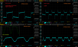
Some tests results as promissed.
I was doing fallowing tests:
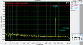
- current consumption at fast square waves with load and without the load
- driver current tests
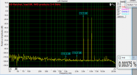
- capactive load test (8R + 0,47uF)
I found that fancy R22 resistor is causing driver instability at the fast transients. Above 50kHz there is a point where current is rising rapidly.
I have changed the base stoppers to 10R and all bad stuff is gone.
I did not have any flames or explosions ( huhh) but I think here was the problem.
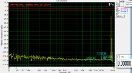
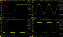
I have applied square at the input of the amp, load 8R and I have adjusted 1A rms current (and than 2A rms current) consumed from the one of the rails. Than I was increasing frequency, from 1kHz to 50kHz the current have the same value and at 100kHz is 1A + 20mA (according to my meter).
Please take a closer look at the driver current wave formos (load 8R), the spikes are much lower. I do not understand all mechanisms here (driver current with sine wave - 2 bottom pictures), but it looks better anyway.
I was doing fallowing tests:
- current consumption at fast square waves with load and without the load
- driver current tests
- capactive load test (8R + 0,47uF)
I found that fancy R22 resistor is causing driver instability at the fast transients. Above 50kHz there is a point where current is rising rapidly.
I have changed the base stoppers to 10R and all bad stuff is gone.
I did not have any flames or explosions ( huhh) but I think here was the problem.
I have applied square at the input of the amp, load 8R and I have adjusted 1A rms current (and than 2A rms current) consumed from the one of the rails. Than I was increasing frequency, from 1kHz to 50kHz the current have the same value and at 100kHz is 1A + 20mA (according to my meter).
Please take a closer look at the driver current wave formos (load 8R), the spikes are much lower. I do not understand all mechanisms here (driver current with sine wave - 2 bottom pictures), but it looks better anyway.
Attachments
Ha, Jason named them "cheapskate" in my honor. 😀
All of his IPS boards were 3"x4". 4"=10.16cm. I asked him to shrink them by 1.6mm so they would qualify for the "proto-type" discount which has a 10cm x 10cm limit. He was kind enough to reduce them for me and dubbed them "Cheapskate" layout to distinguish them from the originals.
Did you see this offer?
PCB Prototype - PCB Prototype the Easy Way - PCBWay
They're doing 4 batches for me right now. Great company to deal with.
They're doing 4 batches for me right now. Great company to deal with.
What is your total cost including shipping? Did you have any 2 oz. boards in there?
I've got some larger boards mixed in on this order so it's $125 with shipping. The small boards are usually $29 to ship to Canada plus duty, brokerage and taxes. You don't pay all the extras in the US from what I understand.
I should add, 10 boards usually ends up to be 11-13 boards. They always throw in a couple extras for free.
I should add, 10 boards usually ends up to be 11-13 boards. They always throw in a couple extras for free.
That is what I was referring to. All three board houses I use have an offer like that.
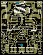
I made a single pair output stage based mostly on Ostripper's layout. I cant tell if layout meets all proper rules for good stability and performance.I would be gratefull if anyone is interested in giving it a try and test it with an oscilloscope. it is about 10mm x 7.9mm
Attachments

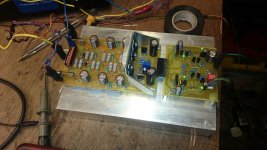
I have finished up the board with motorola output (10R base stoppers). Amp is playing whole morning (couple hours so far). All looks fine, the driver current curves are looking a bit differend than on toshiba OP transistors (the input capactance of the OP transistors make's a difference I think). I have checked the capactive load too - all is fine.
I have soldered together the apex A9 IPS (A9-Ratchet, small and easy). I have lovered the front stage bias to 1mA, inserted double to92 VAS (6,5mA total) and added RC network inbetween the 15V zener supply.
Sound is really good with OPA2134 as an input amp. The offset is bellow 1mV all the time and servo is fast (220kR@10uF). The IPS is playing with new board anyway.
I am so puzzled why Terry's board is making troubles. Maybe the NFB rute is a bit differend ?
Attachments
-
 thd15v2.png26.6 KB · Views: 153
 -
 imd.png38.4 KB · Views: 120
 -
 345k.png42.3 KB · Views: 145
 -
 5k.png41.9 KB · Views: 141
 -
 1k.png41.4 KB · Views: 151
 -
 A9-Ratchet scope readings.png113.1 KB · Views: 207
 -
 DSC_3790.jpg147.9 KB · Views: 225
 -
 DSC_3792.jpg133.6 KB · Views: 217
 -
 motorola OPS.png136.3 KB · Views: 462
I have finished up the board with motorola output (10R base stoppers). Amp is playing whole morning (couple hours so far). All looks fine, the driver current curves are looking a bit differend than on toshiba OP transistors (the input capactance of the OP transistors make's a difference I think). I have checked the capactive load too - all is fine.
I have soldered together the apex A9 IPS (A9-Ratchet, small and easy). I have lovered the front stage bias to 1mA, inserted double to92 VAS (6,5mA total) and added RC network inbetween the 15V zener supply.
Sound is really good with OPA2134 as an input amp. The offset is bellow 1mV all the time and servo is fast (220kR@10uF). The IPS is playing with new board anyway.
I am so puzzled why Terry's board is making troubles. Maybe the NFB rute is a bit differend ?
Peter, very cool - thanks for sharing. The whole exercise with OPS is rather interesting - I'm watching it from the very beginning.
Let's see if Terry's one gets tamed - now I'm sure it will 😉
Thanks Val
Monday i will solder the drivers and the OP transistors supply together and measure the drivers current again to compare.
BTW I have never seen the RC network between the fallowing stages in EF3, usually all three sections have common supply point.
Lerning process sometimes is hard but once it goes forward all is good.
Regards
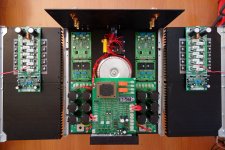
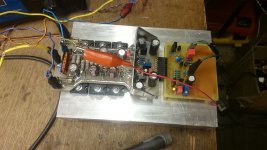
Good!OPS boards are finally on the "production" heatsinks 😎
The holes were drilled not as precisely as I expected, but acceptable, and what I really like - it's done.
Time for some more wiring. Fat wire is in stock already 😉

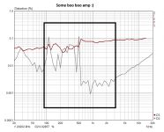
Hi borys ,i can't understand why STEPS graph is a linear graph.Are you sure that is with load connected?I have finished up the board with motorola output (10R base stoppers). Amp is playing whole morning (couple hours so far). All looks fine, the driver current curves are looking a bit differend than on toshiba OP transistors (the input capactance of the OP transistors make's a difference I think). I have checked the capactive load too - all is fine.
I have soldered together the apex A9 IPS (A9-Ratchet, small and easy). I have lovered the front stage bias to 1mA, inserted double to92 VAS (6,5mA total) and added RC network inbetween the 15V zener supply.
Sound is really good with OPA2134 as an input amp. The offset is bellow 1mV all the time and servo is fast (220kR@10uF). The IPS is playing with new board anyway.
I am so puzzled why Terry's board is making troubles. Maybe the NFB rute is a bit differend ?
thimios
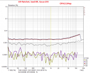
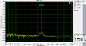
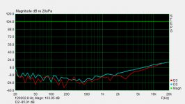
Yes the load is connected, the graph in STEPS looks linear but at higher F the distortions are rising up a bit. At the higher amplitude THD is rising too, but amp sounds really OK.
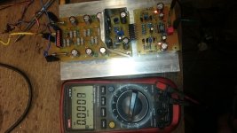
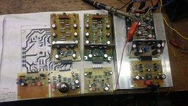
I am doing STEPS graphs to see if the amp has the same harmonics spectrum threw all audio band. Take a look at my setup bellow (you can see the ''linear'' graph on the laptop and 8R resistor and the clamp meter).
Sometimes thd graph is showing some design problems. For me THD figure does not mater much but I like to test it anyway to confirm that all is ok.
BTW
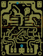
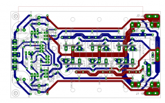
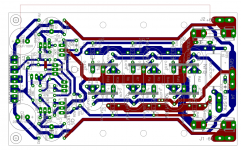
I will make double layer OPS prototype just for my learning process, heavy current track are as close together as possible. The PCB can be cut to make more room for the OP tranies.
regards
Yes the load is connected, the graph in STEPS looks linear but at higher F the distortions are rising up a bit. At the higher amplitude THD is rising too, but amp sounds really OK.
I am doing STEPS graphs to see if the amp has the same harmonics spectrum threw all audio band. Take a look at my setup bellow (you can see the ''linear'' graph on the laptop and 8R resistor and the clamp meter).
Sometimes thd graph is showing some design problems. For me THD figure does not mater much but I like to test it anyway to confirm that all is ok.
BTW
I will make double layer OPS prototype just for my learning process, heavy current track are as close together as possible. The PCB can be cut to make more room for the OP tranies.
regards
Attachments

Last edited:
I got the dual layer small OPS up and running, the performance has improved a bit (I hope)
V+ and V- rails are as close as possible, small current tracks are screaned with ground track now, ground returns are separate, speaker GND is taken from the main PSU (as in apex amplifiers). Transistors are easy to mount now.
The only problem is that the board is not easy to make.
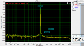
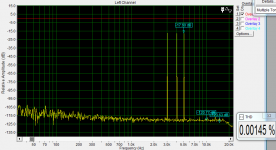
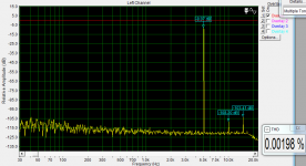
Bellow few screanshots from Cliffjumper (99% finished edition). THD measures are taken with 8R load and 15V Vp-p.
V+ and V- rails are as close as possible, small current tracks are screaned with ground track now, ground returns are separate, speaker GND is taken from the main PSU (as in apex amplifiers). Transistors are easy to mount now.
The only problem is that the board is not easy to make.
Bellow few screanshots from Cliffjumper (99% finished edition). THD measures are taken with 8R load and 15V Vp-p.
Attachments

Last edited:
- Home
- Amplifiers
- Solid State
- SlewMaster Builds