OK so the difference is the mounting hole for the larger device? Seems that could just be drilled into the existing boards. Any other changes?
The plastic body of the part is larger and longer for double di as for Renesas. Double die has package from MJL3281/1302 and i wanted that output fit under board the more i can so due To264 package i had to move pin pad more to the middle of the board.
Marc
Idefixes,
since you are talking about double die ALF parts would these be equivalent to two pairs of output devices with two of these on your new board layout? Just curious if I am understanding correctly.
since you are talking about double die ALF parts would these be equivalent to two pairs of output devices with two of these on your new board layout? Just curious if I am understanding correctly.
Idefixes,
since you are talking about double die ALF parts would these be equivalent to two pairs of output devices with two of these on your new board layout? Just curious if I am understanding correctly.
Yes it's rigth that. Single die are rated at 8A as double die are rated at 16A. So no need to match to single die. Double are those that lazy use in his first one. Exicon has the same parts
Marc
Marc,
Thanks for the answer. Now you have me curious if LC used these also in his VSSA design? I have a pair and will take a look.
Thanks for the answer. Now you have me curious if LC used these also in his VSSA design? I have a pair and will take a look.
Marc,
Thanks for the answer. Now you have me curious if LC used these also in his VSSA design? I have a pair and will take a look.
Not in VSSA (=> ALF08NP16 : N and P die in one package) but in First One (=>ALF16N16 and ALF16P16 : 2 die in parallel in same package)
Marc
Here is the version i will probably build. I don't need extreme power range as my listening room has only 15m². So 2 pairs either Vfet or BJT (MJL3281/1302 or 2SC2922/2SA1302) will be more than enough at +/-50Vdc rail to drive even 4 ohms speakers. I have KSC2690/KSA1220 for cap mu, KSC3503/KSA1381 and 2SC4793/2SA1837 for pre driver and driver in stock. For OP i have matched IRFP240/9240 and MJL3281/1302 in stock but i would give a try to genuine 2SC2922/2SA1216 (purchase from Profusion PLC)
Attachments
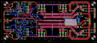
Here is the version i will probably build. I don't need extreme power range as my listening room has only 15m². So 2 pairs either Vfet or BJT (MJL3281/1302 or 2SC2922/2SA1302) will be more than enough at +/-50Vdc rail to drive even 4 ohms speakers. I have KSC2690/KSA1220 for cap mu, KSC3503/KSA1381 and 2SC4793/2SA1837 for pre driver and driver in stock. For OP i have matched IRFP240/9240 and MJL3281/1302 in stock but i would give a try to genuine 2SC2922/2SA1216 (purchase from Profusion PLC)
Look great! I'm sure you will be very pleased with this. Now you just have the task of settling on an IPS. I have built them all and there isn't a bad one in the bunch. Well, maybe the Krypton-V. That includes Valery's and Borys' IPS. This is DIY heaven.
Blessings, Terry
Look great! I'm sure you will be very pleased with this. Now you just have the task of settling on an IPS. I have built them all and there isn't a bad one in the bunch. Well, maybe the Krypton-V. That includes Valery's and Borys' IPS. This is DIY heaven.
Blessings, Terry
Yes Terry,
I have board for CFA-XH, Wolverine, and plan to send to etching house Borys VSHA IPS and Ratchet A9...
Look great! I'm sure you will be very pleased with this. Now you just have the task of settling on an IPS. I have built them all and there isn't a bad one in the bunch. Well, maybe the Krypton-V. That includes Valery's and Borys' IPS. This is DIY heaven.
Blessings, Terry
Me and thimios "fixed" the "V". He said it sang with glory and " you have
make the PCB for it ! "
The present "V" is fully stable and functional ("sansui classic version").
The only design I "shelved" was the "Infidel". 🙁
OS
Sorry, maybe I misremembered. Maybe it was the infidel. I have a huge stack of IPS now. I will have to dig through it and find the K-V. I'll get back to you.

Was the problem solved with Terry burning down a number of components while using the input section from Borys and is this the same input section that Thimios has just mentioned? I don't remember Borys doing a Vacuum tube input section.
Please Kindhornman look here.http://www.diyaudio.com/forums/solid-state/264243-very-simple-hybrid-ampifier-15.htmlWas the problem solved with Terry burning down a number of components while using the input section from Borys and is this the same input section that Thimios has just mentioned? I don't remember Borys doing a Vacuum tube input section.
Post #142
Hi Steven,
Yes the flaming resistors had to do with the OPS not the IPS. Borys hybrid IPS (VSHA) works very nicely. He is in the process of designing one for the ECC88 as well. I like the sound a lot. IT seems to have some added harmonics in the upper mids that sound pretty cool. A fun and easy build.
I built new OPS on a little different layout and now all is fine. I have to say that Borys' system rivals the Slewmaster in sound. I'm having a great time building them.
Blessings, Terry
I would have thought that the vacuum tube would require much higher voltage to function than the solid state devices?
Terry,
So the Borys amplifier is using a different output section than OS's Slewmaster or just a different layout?
Terry,
So the Borys amplifier is using a different output section than OS's Slewmaster or just a different layout?
I see the dreaded word "flaming" and such ....

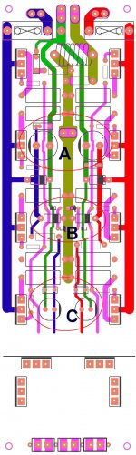
What keeps it all together is the local driver decoupling and the general
layout. (below A and C).
A = the main decoupling , C= the driver decoupling. On this one , all this
dirty decoupling can stay right where it belongs - between the outputs
and rails.
B is the added 3-4A Diode protections AND gate protection for MOSFETS.
This OPS will not have any G1 (dirty) past where the green traces are.
I even think I can fit the cap multipliers on the output side. Just the
Vbe and predrivers will have a very "quiet neighborhood" to unleash
all that POWER ! Multiplier caps and final decoupling will be the clean
G2 that is either separate or taken from the center of G1.
My attempt a year ago to play by these rules worked out well - no
 .
.
This is the "next generation" (bigger and more "anal" 😱 ) - here we
might actually have (the biggest and longest 😀😀 ) ... MT-200's.
OS
What keeps it all together is the local driver decoupling and the general
layout. (below A and C).
A = the main decoupling , C= the driver decoupling. On this one , all this
dirty decoupling can stay right where it belongs - between the outputs
and rails.
B is the added 3-4A Diode protections AND gate protection for MOSFETS.
This OPS will not have any G1 (dirty) past where the green traces are.
I even think I can fit the cap multipliers on the output side. Just the
Vbe and predrivers will have a very "quiet neighborhood" to unleash
all that POWER ! Multiplier caps and final decoupling will be the clean
G2 that is either separate or taken from the center of G1.
My attempt a year ago to play by these rules worked out well - no
.This is the "next generation" (bigger and more "anal" 😱 ) - here we
might actually have (the biggest and longest 😀😀 ) ... MT-200's.
OS
Attachments
I would have thought that the vacuum tube would require much higher voltage to function than the solid state devices?
Terry,
So the Borys amplifier is using a different output section than OS's Slewmaster or just a different layout?
Hi Steven,
Borys developed a set of IPS and OPS that are similar to the Slewmaster but the OPS has a different layout and circuit. Borys didn't have a problem with his OPS but I couldn't get it to work properly. He revised the layout and now I have working boards. I like it because it is a little less that 3" wide and it has 6 outputs that don't extend past the sides of the board. This will fit in a 2u case.
They are sectional just like the Slewmaster and he has at least 4 different IPS designs. The connections are set up a little differently but I have been able to use them with the Slewmaster OPS and vis-a-versa.
You might want to peruse his threads. It is an interesting read. If you are looking for small footprint, he has a tiny IPS called CFP Madness.
Blessings, Terry
Thanks Terry. What is the name of the thread that Borys has? I didn't realize that he had a different output section than the Slew, I thought he had just changed the board layout and moved the components moving the outputs inboard.
I think my heatsink would be considered a bit wider than a 2U heatsink. They are 4" wide but that is really the horizontal dimension, the vertical is about 12 1/2" I've determined that I am going to use 150 watts max in my design. That will be a 120 watts for the bass mid and 30 watts for the dome tweeter. I figure max of 15 watts on the tweeter and max of 60 watts on the bass should be in the 104db range which is plenty loud. You could push it to about 107db with full output. I'm going to assume that the 4"x12 1/2" extrusions should be able to handle 75 watts total continuous output from two amps distributed across that size should work. With this much power the speakers will never be pushed, they will be cruising at this max output.
I think my heatsink would be considered a bit wider than a 2U heatsink. They are 4" wide but that is really the horizontal dimension, the vertical is about 12 1/2" I've determined that I am going to use 150 watts max in my design. That will be a 120 watts for the bass mid and 30 watts for the dome tweeter. I figure max of 15 watts on the tweeter and max of 60 watts on the bass should be in the 104db range which is plenty loud. You could push it to about 107db with full output. I'm going to assume that the 4"x12 1/2" extrusions should be able to handle 75 watts total continuous output from two amps distributed across that size should work. With this much power the speakers will never be pushed, they will be cruising at this max output.
Terry , I know you like the small OPS's .... but
with no cap multiplier , once you get a lot of ripple fed back to a IPS ....
Let me explain - it is degenerative - to a point , it will degrade stereo separation. That is the SQ part.
Then with REAL abuse , you might even effect the whole stability of
the loop.
I was surprised by the "across the board" stability of all my builds. But ,
I found it was the cap multiplier that kept the CFA's stable with the
30-40db isolation from that dirty ol' OPS.
Amps like the VFA's can negotiate well without a multiplier , be stable
like the Badger. They are naturally like this. Watch out with the simple
CFA's , they like clean supplies.
OS
- Home
- Amplifiers
- Solid State
- SlewMaster Builds