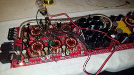
Here's my test rig I made does it look correct I tried my best to build off the info in type 3.
Attachments

I think it's right. The 1157 is in a different location but should work.
There is virtually no way tat you can do any damage connecting this to the amp so connect it and see if you get the ±15v.
Be sure to connect the positive and negative rectifiers to the right points.
This may seem like a pain right now but after you do it a couple of times, it will take about 2 minutes to set up and it's worth the reduced risk to the outputs and drive stage.
If the primary and secondary grounds aren't directly connected, you may need to place the black probe on the secondary ground.
Yea its a little confusing at times but i want to learn this stuff so bad sometimes i get to a head of myself in my head lol.
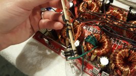
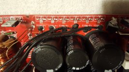
However I am a little unsure were the positive and negative rectifier outs go on the board and dont want to do it backwards
The original rectifiers have same facing diodes so I'm alil thrown can you tell me were my positive and negative would go
Pics below
On the test rig the red wire from diode is positive out and black wire off other diode is negative output? That's what I'm getting in my head.
Attachments

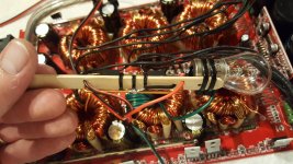
The positive rectifier from the LV jig will go to the pointy end of one arrow. The negative output from the jig will go to the other outer terminal.
Confirm that the positive output connects to the rail cap positive terminals and the negative output connects to the negative side of the rest of the rail caps.
Confirm that the positive output connects to the rail cap positive terminals and the negative output connects to the negative side of the rest of the rail caps.
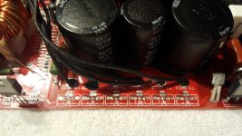
Okay I figured it out I do have a question am I only using the LV Supply on half the rail caps do I need to jump over and power the left side rail caps.
If I'm on the primary in the pic below where is the secondary ground?
Sry for so many questions
If I'm on the primary in the pic below where is the secondary ground?
Sry for so many questions
Attachments

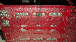
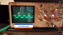
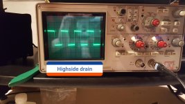
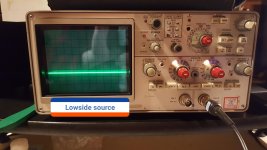
If I measure in dc on the dmm on the outputs I get the following. lowside Source leg I have -16.78vdc and lowside gate -11.47vdc and on the highside drain I have 16.86vdc
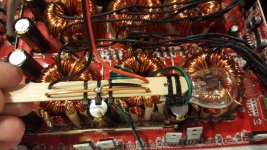
I moved from the primary to what I think mite be the secondary in pic below
I moved from the primary to what I think mite be the secondary in pic below
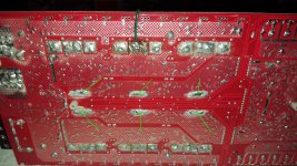
Ok thats where i moved it to so thats good to know and this how it's hooked up
Attachments
Last edited:
Just wondering if that sounds about right for voltage measurements for the outputs on the LV supply
The rails are about right but a DC voltage on the gate doesn't tell me much. Does it have a drive signal?
What frequency?
Do you have rail-rail oscillation?
What frequency?
Do you have rail-rail oscillation?
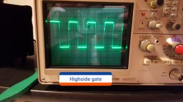
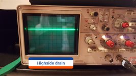
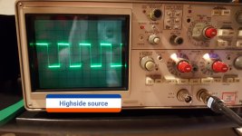
Here's the waveforms in pics below.
It appears I have rail-rail
How do I see the frequency my scope dosent tell me?
SCOPE SETTINGS ARE 10V 10US
It appears I have rail-rail
How do I see the frequency my scope dosent tell me?
SCOPE SETTINGS ARE 10V 10US
Attachments
Last edited:
It looks good.
Are all of the outputs running cool?
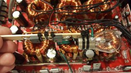
Twist the output filter inductors to see if any have intermittent shorts.
Do both channels work on your scope?
Do you have two matched probes?
Are all of the outputs running cool?
Twist the output filter inductors to see if any have intermittent shorts.
Do both channels work on your scope?
Do you have two matched probes?
Yes the outputs are running cool
Channel A on my scope isn't right it went out on me so I'm using side b for now.
Nothing seems to happen when I twist and pull on inductors
Channel A on my scope isn't right it went out on me so I'm using side b for now.
Nothing seems to happen when I twist and pull on inductors
Sometimes, the controls get dirty. They're (from what I read), not the typical control that wipes to self clean. The wiping wears controls out. The Tek controls are cam driven that pushes a contact down with no wiping. That makes them last nearly forever but if a piece of trash gets in them, it has to be removed.
The scope probes are 4/$20 on ebay. They're good enough for amp work.
The reason I wanted to know if your scope had both channels was to use it in differential mode to check the high-side drive. It's likely OK but if you could check it, why not.
The scope probes are 4/$20 on ebay. They're good enough for amp work.
The reason I wanted to know if your scope had both channels was to use it in differential mode to check the high-side drive. It's likely OK but if you could check it, why not.
Ok I'll have to get another probe for the future it didn't come with one so I'm using the one from my old velleman hps40.
It does play sound but it's making a lot of screeching sound as well as soon as relays engage it's screeching but is playing pretty strong for only LV
It does play sound but it's making a lot of screeching sound as well as soon as relays engage it's screeching but is playing pretty strong for only LV
- Home
- General Interest
- Car Audio
- Skar audio RP4500 need help!