
My previous posts about the SIT "sweet spot" and the various circuit equations have dealt with the small signal behavior of the SIT and mu follower, at around the 1 Watt power output level.
I am finding it much more difficult to understand the large signal behavior where the circuit is reaching the class A limits and beyond, which requires a good large signal device model for the mu follower NFET, and the SIT.
More to follow.
I have some experience probing large signal loudspeaker modeling/measurements vs small signal modeling/measurements.
Any large signal model that is good at predicting large signal behavior is extremely more complicated than the small signal model. Numbers of elements in the model are maybe 10X the number of elements in the small signal model. Moreover, the added elements are nonlinear and possibly non-symmetric.
For a loudspeaker, the inductance is large when the voice coil is near the magnet and small when the coil is farthest from the magnet.
I am sure there are analogs of this type of phenomenon in a FET where a large signal parameter is nonlinear and non-symmetric. Not being a device physicist, I have no first principal knowledge.
SIT MU Follower Large Signal Behavior
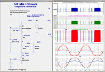
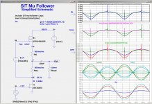
Here are some interesting simulations showing the behavior of the mu follower output stage for a variety of circuit parameters. These simulations agree fairly well with actual bench tests, even though the 2SK182ES SPICE model is in poor agreement with my actual devices.
Although the circuit shown below has been maximally simplified, it captures the behavior of the real circuit. The simulations show that at high power levels the mu follower current gain (beta) an the dynamic load on the SIT (RL) are not constant.
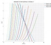
The plots below are at 1 Watt, 25 Watts, and 45 Watts into an 8 Ohm load. From top to bottom the plots are: RL, beta, gme, Id(M1) and Id(J1), and V(Y).
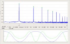
In the first image, the mu follower operates as a constant current source, where beta and RL remain constant. The amplifier clips slightly before reaching 25 Watts. This is representative of the FirstWatt SIT-1.
The remaining images show the behavior for different combinations of Rmu, Rhi, I0, and X0.
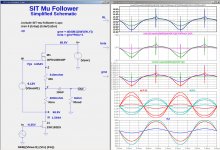
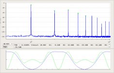
The 2nd image is the left channel of my build shown in posts #16-#19, with Rmu=0.447R Rhi=0.266R. What should be noticed is how much gme, beta, and RL vary at high power levels.
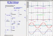
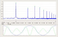
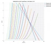
The 2nd and 3rd images show simulations of the left channel and right channels respectively of my build shown in posts #16-#19. What should be noticed is how much gme, beta, and RL vary at high power levels.
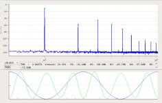
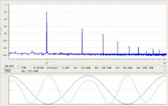
The 4th image shows a simulation at a much lower beta of around 1.26.
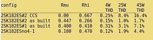
The last image constains a summary of the THD levels in the simulation.
Conjecture:
As beta increases, the mu-follower behavior will differ from the pure single-ended triode of the FirstWatt SIT-1, probably affecting how it sounds. The design goal should probably be to keep beta as low as possible consistent with achieving a given power level wuithput clipping.
Here are some interesting simulations showing the behavior of the mu follower output stage for a variety of circuit parameters. These simulations agree fairly well with actual bench tests, even though the 2SK182ES SPICE model is in poor agreement with my actual devices.
Although the circuit shown below has been maximally simplified, it captures the behavior of the real circuit. The simulations show that at high power levels the mu follower current gain (beta) an the dynamic load on the SIT (RL) are not constant.
The plots below are at 1 Watt, 25 Watts, and 45 Watts into an 8 Ohm load. From top to bottom the plots are: RL, beta, gme, Id(M1) and Id(J1), and V(Y).
In the first image, the mu follower operates as a constant current source, where beta and RL remain constant. The amplifier clips slightly before reaching 25 Watts. This is representative of the FirstWatt SIT-1.
The remaining images show the behavior for different combinations of Rmu, Rhi, I0, and X0.
The 2nd image is the left channel of my build shown in posts #16-#19, with Rmu=0.447R Rhi=0.266R. What should be noticed is how much gme, beta, and RL vary at high power levels.
The 2nd and 3rd images show simulations of the left channel and right channels respectively of my build shown in posts #16-#19. What should be noticed is how much gme, beta, and RL vary at high power levels.
The 4th image shows a simulation at a much lower beta of around 1.26.
The last image constains a summary of the THD levels in the simulation.
Conjecture:
As beta increases, the mu-follower behavior will differ from the pure single-ended triode of the FirstWatt SIT-1, probably affecting how it sounds. The design goal should probably be to keep beta as low as possible consistent with achieving a given power level wuithput clipping.
Attachments

Here is a zip file for the simulations in the previous post. Unzip the file into a directory. Edit the file SIT-mu-follower-1.spc to select various simulation configurations. Experiment with your own parameter sets. Learn more LTSpice plot capabilities by understanding the GME, BETA, and RL plots.
Attachments

Conjecture:
As beta increases, the mu-follower behavior will differ from the pure
single-ended triode of the FirstWatt SIT-1, probably affecting how it sounds.
The design goal should probably be to keep beta as low as possible
consistent with achieving a given power level without clipping.
SIT-2 prototypes explored this behavior and I ended up with a value
that was close to a constant current source.
While not using a mu follower, the SIT-3 exhibits a similar sort of
behavior, and the result is a preference for loads in the 4 to 8 ohm
region, even though it measures well at higher impedances.
Questions for the "Greedy Boyz":
The SIT mu follower with a perfectly linear device for the NFET M1 would preserve single-ended triode behavior. A good NFET with a lot of degeneration would probably suffice and provide push-pull power output.
How about a SIT circlotron? It might be an expensive use of unobtainium SITs, but it would have pure triode push-pull characteristics without output transformers.
Mr. MR made it recently , if I remember correctly ....... aha , here: V-FETRON | AudioMaker
though , killing 2nd, isn't that thing which we want to avoid ?
though , killing 2nd, isn't that thing which we want to avoid ?
ZM: You are right about killing the 2nd harmonic. Push-pull triodes would definitely be different from a single-ended triode.
Back to the mu follower:
Suppose we have a mu-follower whose active device (NFET) is "perfectly linear", i.e. has constant gain, even at high beta values. The dynamic load impedance RL seen by the SIT is:
RL = beta*Rload + Rmu
where Rdrain is the SIT drain impedance mu/gm at the operating point. Rdrain will change with large signals.
Thus the SIT sees different load lines for different values of beta.
The mu follower output impedance is:
Zout = (Rmu+Rdrain)/beta
How might RL and Zout affect to perceived sound? I would expect lower Zout to be better, but what about higher RL?
please , confirm my logic (did I got it , or I'm Dodo as usual):
-whatever we do with transfer characteristic of Mu Follower , it results in "just" fine-tune of entire circuit behavior , simply because we still have two much more dominant things:
-final Rload - speaker,
-Rail value
...... that's at least what I concluded , both from your musings and from my bench exercises .....
now, regarding symmetrical circuits with SIT (circlotron or whatever) - I had my share of time and energy and stubbornness , to achieve intended amount of asymmetry in Papa's SUSY, when I made Babelfish Aleph XJ ; I believe I spent month worth time simulating how to get that , in best , easiest and most controlled way
so, if I made it with that , anyone is able to do the same with any circuit in the world ........ thus we can expect that we can make even circlotron with deliberate inherent flaw,resulting in nice triodish transfer characteristic
but , even then , it is to expect that we must choose most proper value for rail and Iq , just to start with best behaving halves , before attending to set them finally , to desired THD spectra
in case of Singing Bush , I didn't start from clean slate, boundaries and goals were already set ; one of important things which I did learn from exercise is - applies both for Singing Bush and for approach you're showing us here , it is important to have pair of SITs closely matched by Ugs , then you can expect to set them similarly and have proper stereo
-whatever we do with transfer characteristic of Mu Follower , it results in "just" fine-tune of entire circuit behavior , simply because we still have two much more dominant things:
-final Rload - speaker,
-Rail value
...... that's at least what I concluded , both from your musings and from my bench exercises .....
now, regarding symmetrical circuits with SIT (circlotron or whatever) - I had my share of time and energy and stubbornness , to achieve intended amount of asymmetry in Papa's SUSY, when I made Babelfish Aleph XJ ; I believe I spent month worth time simulating how to get that , in best , easiest and most controlled way
so, if I made it with that , anyone is able to do the same with any circuit in the world
........ thus we can expect that we can make even circlotron with deliberate inherent flaw,resulting in nice triodish transfer characteristicbut , even then , it is to expect that we must choose most proper value for rail and Iq , just to start with best behaving halves , before attending to set them finally , to desired THD spectra
in case of Singing Bush , I didn't start from clean slate, boundaries and goals were already set ; one of important things which I did learn from exercise is - applies both for Singing Bush and for approach you're showing us here , it is important to have pair of SITs closely matched by Ugs , then you can expect to set them similarly and have proper stereo
Last edited:

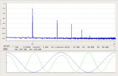
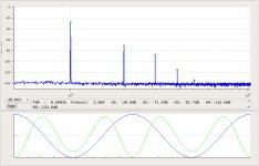
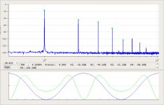
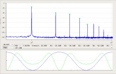
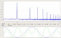
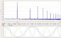
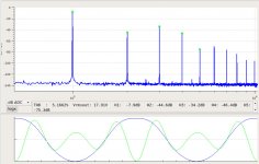
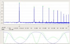
I am posting some measurements I made today one of my 2SK182ES SITS in a mu-follower with no gain. It should behave much like the FirstWatt SIT-1 with the SIT Vds adjusted for an H2 minimum into a 6R load. The bias current is 2.5A.
The first set of plots is into an 8R load at 1W, 16W, 25W and 40W.
The first set of plots is into an 8R load at 1W, 16W, 25W and 40W.
Attachments
This second sets of plots is into an 4R load at 1W, 16W, 25W and 40W. Again at 2.5A bias current.
Attachments
.......in a mu-follower with no gain.....
just to rehash that, for us less talented in 3R - that means plain CCS (no current gain in load)
🙂
Yes. The output capacitor was connected to the bottom on the resistor ladder -- the drain of the SIT. I will show some additional spectral measurements with a modest mu follower gain of beta=4/3. This means the PPR (pullupAC/pulldownAC ratio) = beta-1 is 1/3.just to rehash that, for us less talented in 3R - that means plain CCS (no current gain in load)
🙂
My six Tokin 2SK182ES SITs all show the behavior shown in post #3 SIT measurements, Mu Follower, and amplifier build. I have been choosing mu-follower parameters so that the amplifier has a sweet-spot with an output load of 6R. This results in similar THD (and spectra) at both 4R and 8R output loads (but with opposite phase of H2).
Plots like shown in post #3 allow one to estimate the SIT operating point (bias current and Vds) for a given amount of mu-follower gain beta=PPR+1. I will explain the procedure is a future post.
There is another, simple way to accomplish all of this, needing no fancy equations and graphs. Use the nichrome wire trick shown in post #17. This allows one to set the mu-follower bias current (end tap connected to mu-follower FET) independently from the mu-follower gain (center tap). After changing the tap adjustments, observe the spectrum while adjusting the SIT drain voltage. I usually do this with a 6R load connected.
Using the resistor designations shown in post #17, PPR can be calculated my making 4 multimeter measurements: Vac(RHI), Vdc(RHI), Vac(Rmu), and Vdc(Rmu).
PPR=(Vac(RHI)/Vdc(RHI)) / (Vac(Rmu)/Vdc(Rmu))
I measure Ibias = Vdc(Rsen)/Rsen, where Rsen is a 0R25 1% resistor in series with the mu-follower drain (not shown in post #17).
.... Use the nichrome wire trick shown in post #17. ......
yup
I did saw that, extremely clever
trick invented probably ages ago, easily forgotten,even by those who used it previously (that would be me - I forgot much more than I know now
)if one is having resistive material not good for soldering , terminal blocks are good enough to make transition to regular copper wire
Here are the spectra for an 8 Ohm load at 1W, 16W, 25W, 40W, and 60W:
Attachments
-
 2SK182ESno4-2.5A-SS8R-1W-8R-spectrum.jpg104 KB · Views: 163
 -
 2SK182ESno4-2.5A-SS8R-16W-8R-spectrum.jpg110.9 KB · Views: 134
 -
 2SK182ESno4-2.5A-SS8R-25W-8R-spectrum.jpg113.4 KB · Views: 112
 -
 2SK182ESno4-2.5A-SS8R-40W-8R-spectrum.jpg105.8 KB · Views: 111
 -
 2SK182ESno4-2.5A-SS8R-60W-8R-spectrum.jpg107.9 KB · Views: 113
- Home
- Amplifiers
- Pass Labs
- SIT measurements, Mu Follower, and amplifier build