pull them, snap on just one (X side) pin, so V pin left free for measurement

Thanks again ZM! Done, and here’s the porn to prove it.

I thought the lettering on the cinemag transformers are on the opposite side of pin 1 so the lettering would be on the inside of the board?
Randy
Randy
Hi Randy - The Cinemags only fit one way. Two of the pins are closer together than any of the others, so you cannot install this any other way.I thought the lettering on the cinemag transformers are on the opposite side of pin 1 so the lettering would be on the inside of the board?
Randy
-Glen

don't care for lettering and I'm not sure at all is it having any significance
pitch between pin 1 and 2 is smaller than between rest of pins
that's clue
find pictorial info somewhere in tips and tricks thread ........... post #62 https://www.diyaudio.com/community/...-building-tips-and-tricks.329316/post-5593518
another useful one - all notes in post #1 ....... https://www.diyaudio.com/community/...ysit-general-building-tips-and-tricks.329316/
While I'm waiting for caps and monoblock chassis and other stuff to arrive, I thought I would start sketching out a wiring plan using the boards Zen Mod provided with the SissySit R.3.
I am going to implement a CLC for each monoblock using 33mF Caps and Hammond 159ZJ chokes. I adapted the Mains NTC boards to work with the F6 PSU diagram, which uses 2 CL-60s from the Mains to the transformer.
I banged out these pictures quickly in MS Paint, so they are crude. After I finished I realized I could have drawn the Mains NTC wiring without having to cross wires on the picture - it's not worth going back to correct
Is there anything tragically wrong with my layout?

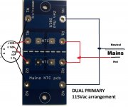
This makes sense, thanks for redrawing this! The drawing I found (and now can’t find) showed an NTC on both the 0 and 120 transformer taps which is what I attempted to duplicate using your boards.cap bank pcb is OK, NTC pcb is tragic
see:
it is irrelevant on which side of primary you put NTC, as long you have intended number of them
illustration - if you have series RC combo, it is pretty much irrelevant is it RC or CR
comprende?

illustration - if you have series RC combo, it is pretty much irrelevant is it RC or CR
comprende?
Si amigo!it is irrelevant on which side of primary you put NTC, as long you have intended number of them
illustration - if you have series RC combo, it is pretty much irrelevant is it RC or CR
comprende?
update: I found the picture. I edited for clarity. This is what I attempted in my illustration…

Last edited:
Before I start stuffing the amp boards with the parts thought of creating a BOM of all the parts included in the kit based on the schematic. Here is the excel sheet for both the channels that I could find on the schematic and I am yet to reconcile this from the kit of parts that mighty zenmod shipped in the package. I believe his kit is top notch with all the parts exactly per the schematic.
I hope I have not done any mistake with the qty and part numbers.
Thanks
I hope I have not done any mistake with the qty and part numbers.
Thanks
Attachments
Documenting my sissysit build hereBefore I start stuffing the amp boards with the parts thought of creating a BOM of all the parts included in the kit based on the schematic. Here is the excel sheet for both the channels that I could find on the schematic and I am yet to reconcile this from the kit of parts that mighty zenmod shipped in the package. I believe his kit is top notch with all the parts exactly per the schematic.
I hope I have not done any mistake with the qty and part numbers.
Thanks
I think its a LT3092 instead of 3062 based on schematic
Wouldn't worry too much about qty, you'll find a place for all the parts, and all the holes should be full when you're done.
Oh yes my eyes need to be blamed 🙂yup, LT3092, it's written loud and clear
@Zen Mod need a clarification with the kit that you sent me, I see that I got 22uf/16v Silmic caps instead of the schematic 10uf/16v for C104/204. I hope 22uf is good enough in this position. Also the C107/108/207/208 schematic says 470uf/16v and I got a slightly different value in the kit. I hope these replacements are good.
Little more progress on R3 today -

Made some cables for the bridge rectifiers to the PSU boards and tested the output voltage with all good so far.

Little more progress on R3 today -
Made some cables for the bridge rectifiers to the PSU boards and tested the output voltage with all good so far.
@Zen Mod need a clarification with the kit that you sent me, I see that I got 22uf/16v Silmic caps instead of the schematic 10uf/16v for C104/204. I hope 22uf is good enough in this position. Also the C107/108/207/208 schematic says 470uf/16v and I got a slightly different value in the kit. I hope these replacements are good.
input Silmic - more the merrier; when I was ordering them I saw that I can get 22u for same price as 10uF, so why not
caps between output gates - whatever I sent you is OK, going from 330uF to 1mF, voltage 6V3 upwards
- Home
- Amplifiers
- Pass Labs
- SissySIT R.3