@zm an input resistor in psu (RCRC) to lower conduction angle w/o small caps isn't used on psu can I ask why ?
clarify - where, what?
on which pcb?
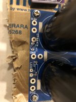
if asking for these on pics, these are not mine and I have no clue, without link to schm
in general, CRC is what I'm using, I can't see no reason for using RCRC
if asking for these on pics, these are not mine and I have no clue, without link to schm
in general, CRC is what I'm using, I can't see no reason for using RCRC
These are the CRC psu boards from @Nisbeth and its meant to be C+C+R+C with on board KBPC type bridge rectifiers. I bypassed the onboard rectifiers and instead using Prasi's LT4320 by shorting the bridge pins to take the +/- inputs from the external rectifier board. Works perfectly well and very stable output voltage.for what I know is better reverse the psu board..... to have diode >18k -R- 18+18k> out
Thanks
Almost finished the amp boards with some improvisation to cut the small TO220 heat sinks fins not to touch the nearby resistors which are pretty closeby. IRF510 used TO220 plastic bushes along with the thermal paste and mica and no shorting anywhere verified with the DMM. The Cinemag xformer was able to fit only one way with the pair of pins exactly matching on the pcb pad holes.


yep but wok better in CRCC ,the amp see double capacity and half ERS ,,,,quite simpleThese are the CRC psu boards from @Nisbeth and its meant to be C+C+R+C with on board KBPC type bridge rectifiers. I bypassed the onboard rectifiers and instead using Prasi's LT4320 by shorting the bridge pins to take the +/- inputs from the external rectifier board. Works perfectly well and very stable output voltage.
Thanks
Almost finished the amp boards with some improvisation to cut the small TO220 heat sinks fins not to touch the nearby resistors which are pretty closeby. IRF510 used TO220 plastic bushes along with the thermal paste and mica and no shorting anywhere verified with the DMM. The Cinemag xformer was able to fit only one way with the pair of pins exactly matching on the pcb pad holes.
you could see on my pics that heatsinks on BD transistors are rotated for 180deg, so no need for cutting 🙂
Mica/isolator needed only for two BDs on same heatsink, you don't need isolator for solo part on heatsink
On holiday, so I don't have the boards here, but iirc I had doubts about some of the clearances so simply mounted a couple of resistors on the underside of the board.
I thought about it but wanted to go by 'T' with the silk screen and works perfectly fine with this arrangement now 🙂you could see on my pics that heatsinks on BD transistors are rotated for 180deg, so no need for cutting 🙂
Mica/isolator needed only for two BDs on same heatsink, you don't need isolator for solo part on heatsink
I meant upside down 180-deg
BD still being properly mounted/entire tab covered with sink, while rest of heatsink upwards
see attached - it's clear some heatsinks mounted "downward" (on mosfet) some "upward" (on BD)
depending of mood, most likely
anyway, you're good, this just for future reference
BD still being properly mounted/entire tab covered with sink, while rest of heatsink upwards
see attached - it's clear some heatsinks mounted "downward" (on mosfet) some "upward" (on BD)
depending of mood, most likely

anyway, you're good, this just for future reference
Attachments
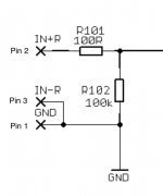
ZM - You got me! 🫢. I will stick with RCA jacks-only. Thanks!nope. this is strictly SE input
IN-R is sorta named just to confuse you
even if it's evidently connected to GND, why not mimicking Papa all the way
From these notes I was following on my first channel got a bit confused with how much Iq should I be aiming for is it 198mV or 160mV as across paralleled 0.11R resistor for 1.8A Iq I need to set for 198mV right?...... or - Look Ma, with no hands,Beast with thousand iterations!!
Logic demands that main schm is here, and all future edits, if and when needed
Few facts, for start, so when you ask, I can point you to this post:
Rails - regular FW Format - in my case that is 300VA Donut per channel, 18+18Vac secondaries, two Graetz bridges per Donut
Iq - 1A7 to 1A8 ...... so dissipation per channel aroundish 80W
Autoformer - Cinemag CMOQ-4HPC
OS - generic ( means don't care which Factory) IRFP9140 and THF51S
Keratherm 86/82 pad for Mosfet, no-name silicon sheet for THF
so, schm (as you can see, it is in fact simplified LuDEF ....... which is logical - this exactly lead me to LuDEF and few other Bstrd amps; stay tuned)
edit on 15.09.2021 - few general setting procedure tips and tricks:
-will not teach ya how to solder everything properly - as always -Assembly of Japanese Bicycle Require Great Peace of Mind
- one tip -SIT gate resistor - R126(226) - best to put shortie (0R) in pcb position, and put resistor itself heatshrinked to end of tiny wire and solder ditto to SIT gate
-prior to powering up, be sure that you have trimpots set properly:
P102 (P202) - irrelevant
P101 (P201) - set to max; confirm with ohmmeter across R104 - in vicinity of 28R
P103 (P203) -irrelevant
P104 (P204) - set to min ; confirm with ohmmeter - improvise where to put probes
- jumpers JP101/201 - open/not mounted
-as always - best to work with one channel connected to PSU at time; in fact - first step just one channel , in second step - you can freely leave powered/connected already set first channel
- one VMeter across output ( DC offset) , second VMeter across any of current sense 0R22 resistors; use mini-clips/probes
- no load on output, input shorted to GND
- power up thingie; observe DC offset - it will rise slowly and everything up to several volts is normal in this moment
observe VMeter across 0R22 resistor - it will be Dodo reading for some long time; after 60-90-120sec - if you don't see any substantial reading , start fiddling with P104 (P204), one turn at time; of course - you did remember where you rotate itr to set to min value, now rotate in counter direction; - don't ask me which - I don't care, I can't remember, simply because I'm always trusting in DMM, not in my memory how to orient damn trimpot to have screw in proper place ....... and my logic what needs to be decreased and what needs to be increased is always ooked, vs. overall consensus
allow 30sec or so between 1-turn steps, to observe when and how much mV you're getting across 0R22
goal is , , say for 1A8 of Iq - 1A8 * 0R11 = 198mV
keep fiddling to get mV creeping up, and once when you see steady rise for each turn, set da thingy to - say 160mV
once when you're there - fiddle with P103 to get as close to 0mV of output DC offset
that would be preliminary setting of OS, now to input buffer setting :
- power off , put mVmeter across R106(206) test pins ; put second mV meter on jumper pin marked "B" and GND
power on, fiddle with P101 to set 20mV across R106(206) ; done - fiddle with P102(202) to set as close to 0mV for buffer output offset ( second
mVmeter) ; when done - power off, close jumper
*************** connect second channel to PSU, repeat entire procedure******************
when done with both channels , power on , re-set Iq of both channels to have 1A8 (Square Law OS is crazy thing) somewhere in temp equilibrium, check output DC offset
slide of both Iq and DC offset - cold vs. hot - is really minimal, but I'm mentioning thermal equilibrium more thinking of importance of final temperature of heatsinks - observe, observe also temperature of outputs , that will give you info/confirmation how good and uniform is thermal interface between parts and heatsink
**************
when done, connect signal, speakers, flip da switch, and enjoy
don't forget Da Porn - no Porn, no Glory

goal is , , say for 1A8 of Iq - 1A8 * 0R11 = 198mV
keep fiddling to get mV creeping up, and once when you see steady rise for each turn, set da thingy to - say 160mV
I could complete the right channel and everything worked as expected with the Iq target set to 198mV (1.8A) as I am using a 5U/400mm chassis. Right now the sinks are nice hot could be because of no air gap being upside down but standing vertical and Chicago weather they should hold on nicely. I could get the DC offset to almost 0.00mV and very stable bias too 198mV.


sorry, still at first morning coffee ...... question is?
if you're just showing off, all good !!
🙂
if you're just showing off, all good !!
🙂
@Zen Mod sorry my question got lost post my pictures 🙂From these notes I was following on my first channel got a bit confused with how much Iq should I be aiming for is it 198mV or 160mV as across paralleled 0.11R resistor for 1.8A Iq I need to set for 198mV right?
goal is , , say for 1A8 of Iq - 1A8 * 0R11 = 198mV
keep fiddling to get mV creeping up, and once when you see steady rise for each turn, set da thingy to - say 160mV
The above is where I had the confusion from the notes of your first post. I have now set the bias to 198mV based on the above 1A8 of Iq - 1A8 * 0R11 = 198mV and ignored the 160mV comment. As I see all the notes references for the Iq being 1.8A so to achieve that on 0.11R its going to be 198mV.
- Home
- Amplifiers
- Pass Labs
- SissySIT R.3


