I thought that 10khz distortion isn't really that important...
It is important that an amplifier can handle frequency components of the order of 10 kHz without producing excessive intermodulation distortion. Of course the best way to test that is by doing intermodulation measurements, but a 10 kHz THD test also gives a rough idea whether the amplifier can handle signals in that frequency range well.
Then being vulgar once more...who needs a third pole at all with less than 0.05% thd at 10 khz?
Anyone who wants to compete with class-D amplifiers with high-order feedback loops and anyone who thinks it's fun to try something different for a change.

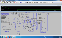
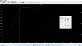
I chequed the step response and the bode plot with the simplified versions...looked fine to me, but honestly i'm not an expert in this kinda stuff.0.05% thd at 10hkz and close to clipping point is decent for any amplifier. Anyway ne5534 seemed to have 3rd pole compensation and almost nobody likes its soud for some reason...I just wanted to see a decent amount of even distortions cause i see no reason in having all that grass up to 1 meghz higher in level than the secod harmonic at 1khz.It is important that an amplifier can handle frequency components of the order of 10 kHz without producing excessive intermodulation distortion. Of course the best way to test that is by doing intermodulation measurements, but a 10 kHz THD test also gives a rough idea whether the amplifier can handle signals in that frequency range well.
Last edited:
I just wanted to play around for a bit...sorry to bother.What i didn't really like was the input resistor divider values which implied more noise at lower frequencies than usual.There's no point in having higher input noise than output distortions...Do you see what you did ? Keep the modifications to yourself when you know nothing. I regret to publish the schematic.
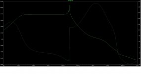
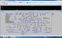
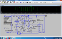
this what i see with no third pole comp, last version...Do you see what you did ? Keep the modifications to yourself when you know nothing. I regret to publish the schematic.
Attachments
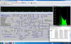
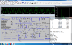
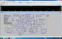
Just some small mods and I actually get better at next to clipping thd, noise, and step response, the only place where the original design gets just a little bit better being the bode plot, difference being small...and i used all your default commands...I spent just a few hours on your schematic, but I let you get the best out of it cause i have better things to do honestly.Besides I never use a .noise command, the noise can be seen on the thd graph ...
Attachments

Last edited:
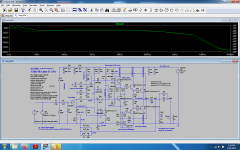
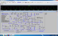
I'm interested what the power-on and power-down transients are like for the real version - I simulated power-on transient and saw out1 ride nearly all the way to 60V before recovering slowly, distorting the signal in the process.I never saw 3P compensated amplifier so I tried to build one. The basic design is come from the local forum's guru, Danhard. I made fine-tuning to adapt it to the real conditions. Three boards were built
Of course single supply amps are usually horrible at power-on and -down, but it strikes me that out1 should climb to 30V or so and not exhibit this behaviour. There are also some very long time constants in the amp, the 220uF C3 in the feedback coupled to the 15k (R7) for instance.
There are lots of commercial amps using turn on and off output delay circuits with relays that can kill any speaker so i wouldn't really care about this type of behavior...
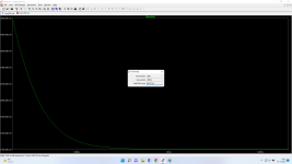
The power-on is very acceptable, the power-off is perfect.
13sec ON
26sec OFF
13sec ON
26sec OFF
That's reassuring. I also noticed that simulating power down without a simulared filter cap was very different and not in a good way!
Not that my opinion is worth much as a total newb, but I really like this project and the motivations behind it (i.e. restricting to "only topology elements known from 60's"). I've been looking to make my first DIY amp and I wanted to make something in a similar form factor as my Creek CAS4040 and yours is the one that speaks to me the most - would it be possible to run something like this in a compact-ish case; even as slim as 1.5U and still keep it cool enough / fit everything?
I’ve built a few amps so not a total noob, but this topology is new to me. I read the links at the beginning of the thread but still don’t understand the principle. What does it mean 3-pole in this context?
intrigued by this low heat high performing circuit that was or could have been made in the 60’s.
intrigued by this low heat high performing circuit that was or could have been made in the 60’s.
A very brief, perhaps overly simplified explanation:
Most amplifiers have their open-loop gain dominated by a single pole; their open loop gain rises at 20dB/decade with decreasing frequency.
Less common are amplifiers with two poles; their open loop gain rises at 40dB/decade with decreasing frequency.
Very uncommon are amps with three pole compensation; 60dB/decade open loop gain. Hence, mention of that gain slope in LKA's opening post.
The opposing religion advocates amplifiers with no negative feedback. 😉
edward cherry wrote about higher order compensation, in order to increase the loopgain in the passband, but to maintain the stability criterion when the loopgain crosses the 0dB.
So this amp's main attribute should be its extreme stability at let's say -1000× , 0x and 1000x gain, right?
- Home
- Amplifiers
- Solid State
- Single supply, three-pole compensated class-B retro amp