Really interesting project, thanks to share schematic!
Does-it sound good ?
of course, it sounds good
full schematic uploaded (1st post)

Interesting - solving the usual class-B problems by maintaining high loop gain at high frequencies. Did you make any measurements pertaining to crossover distortion (e.g. thd at very low power)?
Great short explanation to help orient. Thanks!A very brief, perhaps overly simplified explanation:
Most amplifiers have their open-loop gain dominated by a single pole; their open loop gain rises at 20dB/decade with decreasing frequency.
Less common are amplifiers with two poles; their open loop gain rises at 40dB/decade with decreasing frequency.
Very uncommon are amps with three pole compensation; 60dB/decade open loop gain. Hence, mention of that gain slope in LKA's opening post.
The opposing religion advocates amplifiers with no negative feedback. 😉
Looks like a member/paywall to that article. But this one is free, and sites the same author:Nested Differentiating Feedback Loops in Simple Audio Amplifiers
JAES Volume 30 Issue 5; May 1982
https://www.linearaudio.nl/sites/linearaudio.net/files/cherry ndfl.pdf

I hope it's OK to share this - I will remove it if it's not.
I created a list of all of the components in an Excel spreadsheet based on the schematic in the first post. If I have anything wrong, please advise and I'll update ASAP.
https://1drv.ms/x/s!AvzFj8fCrWcFgpEjywm3CmvUR7oY0Q?e=cHKx7z
Or here's a screenshot for people nervous about clicking a link from a forum newcomer 🙂
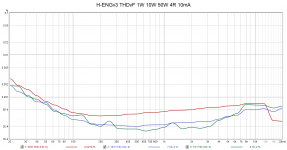
measurements - THD vs Freq at 1W 10W 50W 4R
output quiescent current 3mA and 10mA (10mA is the maximum without emitter resistors)
I'm feeling a bit mean here, but I'm noticing a rising distortion characteristic at higher frequencies for the 1W/3mA plot - more so than for the higher-power traces.
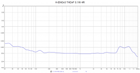
If this is indicative of crossover distortion, then a plot for 100mW could be very revealing.
As I say, I feel a bit mean because I think the work you've done here is really useful.
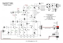
Yes, crossover distortion is present, what counts is the amount. What level would you satisfied ?
I can show you a simpler retro amp with very good performance, the DanWatt (class-b, current driven, designed by Danhard)
Attachments

Last edited:
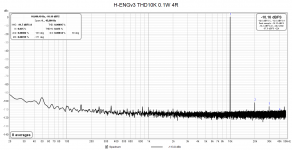
Well, the fact that the increase in thd at 100mW is modest, relative to 1W, seems to me to show that crossover distortion is being controlled remarkably well. So I would have thought it completely inaudible for all programme material - by quite a margin.Lots of expectations ... it's a simple retro low-end amp. THD10K 0.001% at 0.1W/4R is bad ? imho not at all
I wasn't being critical, by the way - just interested in what seems to me to be one of the main reasons for wide open-loop bandwidth. Obviously, I wasn't expecting zero crossover distortion, as the hf feedback is there to reduce, not remove. Nevertheless, who needs those many exotic topologies if we have such a relatively straightforward solution?
On the other hand, we have verified directly coupled topologies with input differential pair that do not depend on bootstraps, output electrolytic capacitors and NFB hard fight with crossover distortion. I do not understand why to return to all those circuit issues that we were trying to avoid in designs after 1970. Nostalgy?
Maybe because very good VFM (Value for money) performance, simplicity and no need for hard available or exclusive components . And performance is very good. It is good to make things as simple as possible, IMO...
On the other hand, we have verified directly coupled topologies with input differential pair that do not depend on bootstraps, output electrolytic capacitors and NFB hard fight with crossover distortion. I do not understand why to return to all those circuit issues that we were trying to avoid in designs after 1970. Nostalgy?
Well, if it measures well enough (in all areas of concern) and is relatively simple, cheap, and easy to source, then why not? By the way, I think output capacitors are a good thing, as they offer intrinsic protection of your expensive speakers. I have them at the output of my (dual-supply direct-coupled) amplifier regardless.
Having said that, the idea of extending the open-loop bandwidth can I'm sure be extended to some of the newer topologies - as appropriate.
Edit: Oops - just spotted your post, Elvee!
And, uncannily, I was intending to cite your good self as a designer of "some of the newer topologies"!
Edit: Oops - just spotted your post, Elvee!
And, uncannily, I was intending to cite your good self as a designer of "some of the newer topologies"!
For me I am attracted because of performance, simplicity of build, novel topology (already built several class-A and assembled class- D modules). I also highly value compactness. No 3U cases with ginormous heat sinks is a big plus.On the other hand, we have verified directly coupled topologies with input differential pair that do not depend on bootstraps, output electrolytic capacitors and NFB hard fight with crossover distortion. I do not understand why to return to all those circuit issues that we were trying to avoid in designs after 1970. Nostalgy?
- Home
- Amplifiers
- Solid State
- Single supply, three-pole compensated class-B retro amp