I was just considering building another amplifier similar to the Ion Obelisk and Nytech when I came across this design. It's like the Nytech circuit but with a lot of extra development!
However I have a couple of questions:
1) Does the 3-pole compensation make it more likely to oscillate with capacitive loads?
2) Are pcbs or gerbers available?
However I have a couple of questions:
1) Does the 3-pole compensation make it more likely to oscillate with capacitive loads?
2) Are pcbs or gerbers available?
I am not the only one who had a toroid that measures more than the spec. I found a thread on the forum about changing the secondary voltage and managed to unwind one of my toroid’s secondaries to give the required voltage. Tested my amp boards with the new 43.7VAC input voltage, but there is still a fault on both boards.
With a 1.06K resistor in the fuse holder I measure 60V before the fuse and still exactly 6V (and not 30V) after the fuse.
What can I measure or do next to try and find the incorrect/faulty part?
With a 1.06K resistor in the fuse holder I measure 60V before the fuse and still exactly 6V (and not 30V) after the fuse.
What can I measure or do next to try and find the incorrect/faulty part?
Thank you. I made up a resistor chain that gives 540R and measured the voltage again - and still get only 6V. Even brought the resistor down to 430R and still only measure 6.1V
I have no idea how to proceed further.
I have no idea how to proceed further.

Thank you for offering to help me. I think I found the problem. P1 and P2 are swapped around. It’s either negligence from my side or the local supplier marked the plastic bags incorrectly, which has happened more than once before. I always double check and measure each and every resistor before soldering, however these two were the ONLY resistors I did not measure.
Now to fix this. I actually hate modifying or replacing soldered components.
Would really like to get this H-ENG amp up and running.
Now to fix this. I actually hate modifying or replacing soldered components.
Would really like to get this H-ENG amp up and running.
Hi LKA,
What is the reason for having the parts in the red circle? Also, what is the purpose of the diodes across the transistors? Thanks!

What is the reason for having the parts in the red circle? Also, what is the purpose of the diodes across the transistors? Thanks!
Also, what is the purpose of the diodes across the transistors?
if i am right...input limiter - T4 should not get more wave of 0,7Vpeak
chris
if i am right...input limiter - T4 should not get more wave of 0,7Vpeak
chris
Confession time. I made an embarrassing rooky mistake by soldering P1 and P2 with the wrong orientation (not swapped around).I think I found the problem. P1 and P2 are swapped around.

So, for the startup procedure my trim pots must be turned fully clockwise first. That made all the difference.
All good now - boards seem to work and bias set to 35mA, ready to be assembled before first sounds.

Getting there slowly.
It happens to the best of us mate. I made a mistake on my H-ENG build too. In my case I had T1 and T2 as BC556B when T2 must be NPN 🤦♂️I made an embarrassing rooky mistake
I'm excited to hear your impressions of the amp. I still use mine and love it.
It’s alive and working! And a huge thanks to member @002 whom I got the boards (and some components) from. At the point when I gave up looking for the mistake he encouraged and helped me to find the fault. Finally got the voltages correctly dialled in and bias set at 35mA.
What does it sound like? Very, very good. I am very satisfied so far. Difficult to say if this amp sounds better or same as my previous Class A amps, but the fine details, tone and overall balance sounds very good. It will take some more serious listening to evaluate the sound stage and imaging, which I haven’t done yet. I like to spend a lot of time listening to most of my familiar music with a new amp, before making any judgement.
The reason I wanted to build an amp with this particular topology is because I wanted very good sound, but without the heat. And I think I have achieved that with this build. I am done with hot Class A amps.
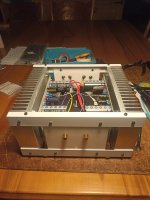
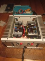
For this amp I re-used the enclosure which housed a Pass ACA (Class A) amp. I called it my Meccano amp. So, the heatsinks are probably a massive overkill for the H-ENG, but that’s ok. As you can see from the pictures (taken very late at night) the space is very cramped inside and I had a hard time fitting the toroid inside too. I pick up a slight disturbance/hum which I think is because of the open toroid so close to the boards and signal wires. Think I will remove the toroid and make an outside shielded ac psu for this amp later.
Thank you @LKA for sharing this special amp with us.
What does it sound like? Very, very good. I am very satisfied so far. Difficult to say if this amp sounds better or same as my previous Class A amps, but the fine details, tone and overall balance sounds very good. It will take some more serious listening to evaluate the sound stage and imaging, which I haven’t done yet. I like to spend a lot of time listening to most of my familiar music with a new amp, before making any judgement.
The reason I wanted to build an amp with this particular topology is because I wanted very good sound, but without the heat. And I think I have achieved that with this build. I am done with hot Class A amps.
For this amp I re-used the enclosure which housed a Pass ACA (Class A) amp. I called it my Meccano amp. So, the heatsinks are probably a massive overkill for the H-ENG, but that’s ok. As you can see from the pictures (taken very late at night) the space is very cramped inside and I had a hard time fitting the toroid inside too. I pick up a slight disturbance/hum which I think is because of the open toroid so close to the boards and signal wires. Think I will remove the toroid and make an outside shielded ac psu for this amp later.
Thank you @LKA for sharing this special amp with us.
Attachments
I have an issue what seems to be a ground loop problem. Just trying to understand and wire everything correctly here. What does "LBC" ground stand for, and how should it be connected and wired to the chassis and PE? I see PE on the schematic, but not the LBC GND.
Thanks.

Thanks.
Do not use LBC (Loop Breaker Connection point). Make sure you only have a single point connection between PCB ground and chassis (at RCA input). Did you use a dual mono arrangement? You should.
It is a great topology. The 2 transistor plus 2 fets delivers 100 watts at 0.005 thd.
A 3rd transistor gives Constant current to VAS transistor knocks down thd more.
A 3rd transistor gives Constant current to VAS transistor knocks down thd more.
Thanks - got mine wired like this.Do not use LBC (Loop Breaker Connection point). Make sure you only have a single point connection between PCB ground and chassis (at RCA input)
Nope - currently sharing a single pair of secondaries for the two boards. I tried to unwind the toroid to bring down the voltage of the secondaries to around 40 VAC but could only manage to do one of the two secondary outputs. Ok, so two toroids on the shopping list for proper dual mono.Did you use a dual mono arrangement? You should.
Thank you for the feedback.
I finally received a new toroid and connected it to my amp this weekend and re-adjusted the bias. Thank goodness the humming noise is gone now!
Only music playing and sometimes I hum along. A wonderful sounding amp, without the heat of Class A.
Only music playing and sometimes I hum along. A wonderful sounding amp, without the heat of Class A.
- Home
- Amplifiers
- Solid State
- Single supply, three-pole compensated class-B retro amp