Normally, for the quiescent operating condition of an Op Amp, the differential voltage needs to be Zero between the + and - input terminals.
That might have both resistors return to ground;
or both resistors return to +3V;
or one resistor returns to + 4V and the other resistor comes from the Op Amp output and the output swings to +4V.
The gain of the Op Amp is very high, so it only takes a very small difference from +4V to make the + and - inputs be essentially equal.
Then, the other factor is input offset specification.
Because Op Amps generally are not perfect, there can be a very small input offset voltage or current that causes the output not to be at zero volts when both the + and - inputs are zero volts with respect to each other.
Often, with a feedback resistor from output to the - input, the output will put out just the right small voltage above or below zero volts, so that the small input offset voltage is automatically compensated for.
Thanks @6A3sUMMER !
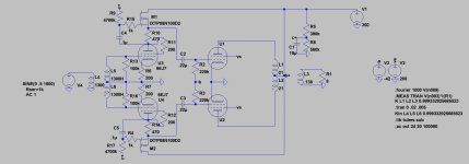
I would like to propose this variation I was simulating yesterday evening.
The feedback squashes the distortion when it becomes very high as pentodes easily do.
Then I've applied 23% UL (it will simplify the PSU as well), obtaining the following:

Rout is 1.35 Ohm that gives a DF of 2.9
0.5% THD at 1 Wrms and 2.9%THD at 10 Wrms
but mainly... it can be easily driven by a DAC without any driver stage.
On top of that, with this feedback configuration, it partially increases the bias current flowing thorugh the tube when the anode is going up, so in fact increasing the available swing on top. I can indeed increase the voltage of the working point and get more power because I increase the power dissipation where it is usually lower.
...so... what am I doing wrong?
I would like to propose this variation I was simulating yesterday evening.
The feedback squashes the distortion when it becomes very high as pentodes easily do.
Then I've applied 23% UL (it will simplify the PSU as well), obtaining the following:
Rout is 1.35 Ohm that gives a DF of 2.9
0.5% THD at 1 Wrms and 2.9%THD at 10 Wrms
but mainly... it can be easily driven by a DAC without any driver stage.
On top of that, with this feedback configuration, it partially increases the bias current flowing thorugh the tube when the anode is going up, so in fact increasing the available swing on top. I can indeed increase the voltage of the working point and get more power because I increase the power dissipation where it is usually lower.
...so... what am I doing wrong?
Attachments
Last edited:
OK...so, after a bit o' time passing, how many ov these beasties have been built? SE or otherwise? And what is the result? The sims sure look pretty brilliant. Have to wonder, if built, are they still in use having been found good performers?
Douglas
Douglas
The amp that I have been listening to for a couple of years is very close to the schematic seen in post #1 of this thread. It runs CCS loaded 7KY6's for the input tubes and 26HU5's for the output tubes with a fixed 150 volt supply for G2 (no UL). I have no issues using mosfet followers or CCS's in my tube HiFi amps, but I don't use mosfets or opamps in positive gain circuits. I get about 15 WPC on about 450 volts. This varies with line voltage. I have not been inclined to tinker with it since it just works. I have seen the audio power meter read over 500 watts with 4 26HU5's in parallel push pull with similar tech, but I have never actually built the BIG ONE (1 KW stereo) as I have no need for it, and I would likely kill my speakers with it.
I have been slowly trying to reinvent the guitar amp, and for that project all means of amplifying or mangling a signal are allowed. I even dug out a box full of germanium transistors for some experiments.
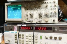
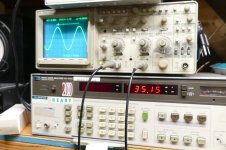
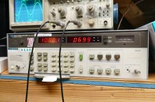
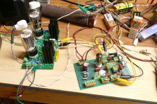
Some experiments intended for guitar amp signal mangling have accidentally led to a unique driver circuit that makes lots of drive voltage with very low THD. I decided to apply the UNSET concept and the SATURATOR ("Gyrator" loaded pentode) used in some of my guitar amp designs to the same circuit. Some tweaking can get lots of gain, really low distortion, or a balance of both. A little $1 tube is seen here making 50 volts RMS of drive at a gain of 50 with 0.07% THD, which is not much more than the residual THD in the oscillator. Feed that into an UNSET output board with both 26HU5's wired in parallel through a crappy old Hammond 1628SEA wired for 2500 ohms and you get 35 watts at 1.22% THD in SE. I may try to splice that back into the UNSET PC board someday. I have enclosed the asc file for those who like to simulate. Some component values have been tweaked since the simulation was done. The tube for these measurements in use is one of the many 7 pin tubes that I tried. Most work well, as do the 9 pin flavors like the 6EJ7, 6KT6, 7KY6 and a few others.
I have been slowly trying to reinvent the guitar amp, and for that project all means of amplifying or mangling a signal are allowed. I even dug out a box full of germanium transistors for some experiments.
Some experiments intended for guitar amp signal mangling have accidentally led to a unique driver circuit that makes lots of drive voltage with very low THD. I decided to apply the UNSET concept and the SATURATOR ("Gyrator" loaded pentode) used in some of my guitar amp designs to the same circuit. Some tweaking can get lots of gain, really low distortion, or a balance of both. A little $1 tube is seen here making 50 volts RMS of drive at a gain of 50 with 0.07% THD, which is not much more than the residual THD in the oscillator. Feed that into an UNSET output board with both 26HU5's wired in parallel through a crappy old Hammond 1628SEA wired for 2500 ohms and you get 35 watts at 1.22% THD in SE. I may try to splice that back into the UNSET PC board someday. I have enclosed the asc file for those who like to simulate. Some component values have been tweaked since the simulation was done. The tube for these measurements in use is one of the many 7 pin tubes that I tried. Most work well, as do the 9 pin flavors like the 6EJ7, 6KT6, 7KY6 and a few others.
Attachments


Hi, I used some GU50, KT88 and 6550 on a 3k and EL34 on 5k Ra.
I've preferred 20% feedback for the first three and the standard 10% shown in the schematic for the EL34.
Every stage with local feedback only. I still need to test the Corr.Diff. feedback directly driving the cathode of the driver.
@Tubelab_com
What would you use as a SS FETSET driver capable of eating 5-10mA?
I would like to try a fully dc-coupled amp:
Can you suggest a nmosfet to be used as a FETSET driver?
I would like it to swing 200Vpp (to have margin on the needs of the output stage, without exceeding SOA of the pmosfet source follower of the output stage).
The idea to use a nmosfet is because it can go down to few volts above its negative reference, that will be few volts below zero, so it should swing close to zero volt, fully driving the output stage to its A1 limits.
I've preferred 20% feedback for the first three and the standard 10% shown in the schematic for the EL34.
Every stage with local feedback only. I still need to test the Corr.Diff. feedback directly driving the cathode of the driver.
@Tubelab_com
What would you use as a SS FETSET driver capable of eating 5-10mA?
I would like to try a fully dc-coupled amp:
- DRIVER:
- the gate of the pmosfet source-follower grounded;
- the drain of the pmosfet source-follower connected to a regulable negative voltage (that sets the bias of the stage);
- the gyrator you have shown here as a load for the nmosfet used as driver;
- the source of the nmosfet of the gyrator dc connected to the gate of the pmosfet source follower of the output stage;
- the Vdc of the gyrator used to bias the output stage.
- OUTPUT STAGE:
- UNSET standard configuration.
Can you suggest a nmosfet to be used as a FETSET driver?
I would like it to swing 200Vpp (to have margin on the needs of the output stage, without exceeding SOA of the pmosfet source follower of the output stage).
The idea to use a nmosfet is because it can go down to few volts above its negative reference, that will be few volts below zero, so it should swing close to zero volt, fully driving the output stage to its A1 limits.
I'm not sure I get the correct picture of your driver stage from the description; a schematic would be helpful.What do you think about it?
My all mosfet two stage FETSET amp uses an IXYS IXTP08N100D2 for the middle fet in the driver stage. It's good for 800 mA at 1000 volts. The CCS is the usual 10M45S, but any suitable depletion fet will work. I have used the DN2540 there too. The output stage uses a FQP9P25 for the P fet and an IXTH6N100D2 (6 amp 1000 volt) for the output part. There is no CCS or gyrator as the N fet drives a 600 ohm SE OPT intended for use with 6C33 tubes.Can you suggest a nmosfet to be used as a FETSET driver.
@Tubelab_com
I know this has probably been addressed quite a number of times, can you explain why you need a depletion fet? I've sim-ed it with a IRF830, what i believe is a enhancement fet (though i realise it is called a Vfet in some literature) and it seems to work just fine. Any comments on a random IRF830 vs the more pricey IXTP08N100D2?
I know this has probably been addressed quite a number of times, can you explain why you need a depletion fet? I've sim-ed it with a IRF830, what i believe is a enhancement fet (though i realise it is called a Vfet in some literature) and it seems to work just fine. Any comments on a random IRF830 vs the more pricey IXTP08N100D2?
The circuit seen in post #244 should work with most fets, depletion or enhancement as the gate voltage comes from a voltage divider. The source voltage will vary by a few volts with the fet change, but that will not affect the circuit much.
The circuit shown in post #1 must use a depletion mode fet for M1, the CCS plate load for the 12GN7. Here the bias voltage is developed across the source resistor in a manner similar to cathode bias on a vacuum tube. For this to work the gate must be more negative than the source in normal operation. This requires a depletion mode fet. Here both Digikey and Mouser have the IRF830 and the IXTP08N100D2 priced at $2.44 for the IRF830 and $3.05 for the IXTP08N100D2. Unfortunately neither vendor had the IXTP08N100D2 in stock.
The circuit shown in post #1 must use a depletion mode fet for M1, the CCS plate load for the 12GN7. Here the bias voltage is developed across the source resistor in a manner similar to cathode bias on a vacuum tube. For this to work the gate must be more negative than the source in normal operation. This requires a depletion mode fet. Here both Digikey and Mouser have the IRF830 and the IXTP08N100D2 priced at $2.44 for the IRF830 and $3.05 for the IXTP08N100D2. Unfortunately neither vendor had the IXTP08N100D2 in stock.
a schematic would be helpful
Just a sketch to explain the point:
- the bias of the driver is set by the negative voltage (set by trimmer B) of the drain of the pmosfet and g1's voltage divider, while the gate of the pmosfet is grounded, so dc coupled to the input;
- the bias of the output stage is set by the voltage of the source of the gyrator mosfet on the driver (set by trimmer A)
Here I sketched a pentode, but a n-mosfet on the driver would help to swing closer to 0 Volts.
Last edited:
thanks for the great explanation, I dread the IXTP part because they are very scarce and fakes a plenty.The circuit seen in post #244 should work with most fets, depletion or enhancement as the gate voltage comes from a voltage divider. The source voltage will vary by a few volts with the fet change, but that will not affect the circuit much.
The circuit shown in post #1 must use a depletion mode fet for M1, the CCS plate load for the 12GN7. Here the bias voltage is developed across the source resistor in a manner similar to cathode bias on a vacuum tube. For this to work the gate must be more negative than the source in normal operation. This requires a depletion mode fet. Here both Digikey and Mouser have the IRF830 and the IXTP08N100D2 priced at $2.44 for the IRF830 and $3.05 for the IXTP08N100D2. Unfortunately neither vendor had the IXTP08N100D2 in stock.
I have attached my rendition of your recipe with 6GE5s as outputs, and 6BN11/6EJ7 as the drivers, any comments? the input trans is 10k: 10k+10k and output load is 6k6 if i did not remember wrongly
Attachments
Joining @Tubelab_com last driver gyrator loaded ( https://www.diyaudio.com/community/threads/of-course-it-will-work-its-guaranteed.419415/ ) and @SpreadSpectrum Corona amp ( https://www.diyaudio.com/community/...ow-distortion-a2-dht-se-amp-prototype.357559/ ), a simple pentode driver - UL output stage idea to be developed. On LTspice gives 1 Wrms at 0.02% THD (mainly 2nd) and 15 Wrms at less than 1% THD with a DF of 7.3

You never get 15 watt with 88and 15 Wrms at less than 1% THD with
It is pure fantasy as LTspice simulation
Walter
Real measured data on an Electro Harmonix KT88 in UL in a Tubelab Simple SE board with a 5000 ohm OPT and about 460 volts of B+gives 15 watts of output but not at 1% THD, more like 3% as the amp is just starting to clip.
The efficency of a s.e. Is 25 % ( theory) so in this case the 88 will dissipate 60 watt that is out of specs
Maybe the KT150 /170 will go close to 15 w
On last proto I done with 150 I got around 9-10 w clean
Walter
Maybe the KT150 /170 will go close to 15 w
On last proto I done with 150 I got around 9-10 w clean
Walter
I’m sorry @waltube , but your theory is again wrong ad for the DF the other day. Class A SE maximum efficiency is 50%, not 25%. 15 Wrms is plenty possible with a 40 W plate dissipation tube, as @Tubelab_com stated.The efficency of a s.e. Is 25 % ( theory)
Class A2 can approach 50% efficiency. I have seen over 40% in an 845 amp running on 1100 volts and making 30 watts. The Simple SE is cathode biased and barely touches A2. I was running 100 mA of cathode current with around 400 volts across the tube for 15 watts at the edge of clipping. I sold that amp, so I can't verify its performance anymore, but I have seen class A efficiency vary from a poor 5% to the 40+ percent number I saw in the A2 transmitting tube amp which could run 211's or 845's. Sold that one too. Current experiments with TV sweep tubes do go beyond 25% though. I also have a class A SE mosfet amp that works through an OPT. It runs in the 30 to 35% range depending on how hot I run it.
I do not expect to have 15 Wrms at 0,89% THD as I got from LTSpice, also because that is on the edge of clipping, so every small variation from simulated perfectionland will make it worse.gives 15 watts of output but not at 1% THD, more like 3% as the amp is just starting to clip.
What can be expected from it is to hear more distortion from the speakers than from the amp. …and some output tranformer distortion on low frequencies at higher wattages as well (I will use Toroidy’s standard 3k SE with 40%UL taps).
NoClass A SE maximum efficiency is 50%, not 25
The 88 as other similar tube have curve up to 0 volt, no positive region
So it is class A and the efficency is 25% to have a reasonable distortion
Running A2 make no sense due the non linear grid current, one issue
But probabile you can’t understand this because you play with simulation
Then I got a misunderstandin of DF as specified there
Walter
So you probably know everything even better than Langford-Smith 🙄But probabile you can’t understand this because you play with simulation
Why you always attack people saying wrong things and showing that you don’t know what you say? Just accept when you do not know something and let it go.
- Home
- Amplifiers
- Tubes / Valves
- Single Ended: the pentode retaliation