I built an AC coupled cathode biased version of Michael Koster's Schadeode using a KT88. I used Bud Purvine 5k transformers gapped for 80 ma. into a 8.4 ohm load. Plate to cathode voltage was 510 volts and cathode current was 80 ma (40.8 watts dissipation). At 1khz distortion was 0.07% at 1 watt, 1% at 10 watts and 3% at 15 watts. Clipping began at 16 watts.
I used a dual channel oscilloscope and a Hewlett Packard 8903A for signal generation and measurements. Surprisingly the efficiency was 37%. I repeated the measurements many times varying the plate voltage and current in search of a compromise between distortion and power output.
The Bud Purvine outputs have the best efficiency by a significant margin of any of the SE transformers that I own. I subbed in other transformers and got less power out by as much as a couple of watts.
Steve

Pentodes and A2 triodes will give similar max efficiencies as they are both capable of reaching saturation.
I got ~44% efficiency with a VT-127A once (42W output with 93W or so plate dissipation). I could have done about the same with a 100W pentode.
I was using toroid output transformers (very low copper loss) for that measurement.
Of course, you can even go above 50% efficiency if you allow for lots of distortion. The 50% limit only applies to an undistorted sine wave.
Here I set dissipation at 35 W to be able to keep Rg1-k at 220k as per KT88 datasheet to preserve the tube from thermal runaway.(40.8 watts dissipation). At 1khz distortion was 3% at 15 watts.
One question to @ArcticBrew and @Tubelab_com : you both used KT88 in SE on 5k and around 500V, while I’ve tried them in UNSET at 450V or fixed/cathode biased below 400V always on 3k. Is it preferrable to make them work on 5k?
Another point I noticed, that I would like to know from more experienced Single Endeders like the two mentioned above, @SpreadSpectrum @6A3sUMMER @jhstewart9 amd others:
With local feedback only, fixing a plate dissipation number, I prefer the sound when it hits Ia=0 before Vg1k=0, so woth slightly higher plate voltages: I don’t know if it is the 2nd harmonic prevalence or the light more powerful feeling that the amp has (that I think it is due to the fact that it is indeed “more powerful” where it has a higher DF (close to Vg1k=0), and on the other side (Ia=0) the speaker is more “free to move”).
With high feedback ratios I prefer when it hits Vg1k=0 and Ia=0 at the same input level, because it stays cleaner at higher wattages.
Generally speaking, I prefer to get the feedback from the output-tube plate rather than output-transformer secondary. It sounds better to me not to have the iron involved in the loop.
The 50% limit only applies to an undistorted sine wave.
For pentode configuration in class A the max efficency is from 28 to 43% for THD less than 10% ( Radiotron, page 562)
to be precise:
BUT
Which is th level of THD to say undistorted? 1% or 3%, the 10% of course is out of the limit.
With 88 there is UL (pseudotriode) configuration in that circuit so we can assume is quite similar to triode and the 25% is the max. If you don't want a distortion generator.
I mean Class A, the 88 doesn't have any curves for A2 in any possible configuration of it
Another problem in to check the THD vs frequency at different level to understand if the working point and the coupling with OT is good enough.
Who play in the real world knows that mainly at low frequency and int high region the coupling between tubes and OT is delicate to get a reasonable curve costant with the different levels at reasonable THD.
And this is the main test to follow.
please can you give me details on circuit? thxI built an AC coupled cathode biased version of Michael Koster's Schadeode using a KT88.
Walter
HiI think it can be done in a carefully-designed practical circuit with less than 1% distortion.
Your is a assumption, I think.
Or there are real lab test done with a stuff ? Giving 15 watt at 1% THD, not 10% or similar.
Not simulation, of course.
Walter
Absolutely not. UL became popular exactly as a compromise between pentode power&efficiency and triode linearity and low rp.With 88 there is UL (pseudotriode) configuration in that circuit so we can assume is quite similar to triode and the 25% is the max.
Stop writing wrong things without any knowledge.
You can start learning from here: https://www.diyaudio.com/community/...ow-distortion-a2-dht-se-amp-prototype.357559/Hi
Your is a assumption, I think.
Incorrect. ArcticBrew above, has achieved 3% at 15W with a KT88. The circuit zintolo is proposing is a heavy feedback circuit that could easily lower the distortion substantially further.Your is a assumption, I think.
I have used a similar circuit to achieve 42W output at 0.5% with a VT-127A, while running the plate at 93W (45% plate efficiency). There is no logical reason to think a pentode output tube would be unable to achieve similar results, although my experience with this type of circuit indicates that there will be more distortion with a pentode than a high-impedance triode.
By the way, there is no magic here. This is just maximizing open-loop gain and using the excess gain to reduce distortion. The authors of the Radiotron Design Handbook just didn't imagine how a high gm pentode and a semiconductor load could be used to bring 30+dB of local feedback to bear on their rules of thumb. I'm not smarter than them, and I'm not breaking any natural laws here. I'm just using more feedback than they imagined would be possible (and so is zintolo).
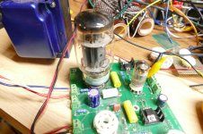
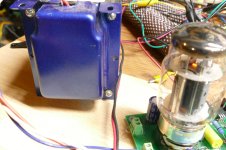
I grabbed Tubelab Simple Single Ended (SSE) board number 1 which was populated in 2006 and used for experiments ever since. Some of these have ended badly with more than one exploded cathode bypass cap due to runaway tubes being pushed far beyond their limits, I hooked the board up to a variable bench power supply that goes to 600+ volts at up to 1.7 amps. I grabbed a 2006 vintage Edcor OPT off the same shelf. Yes, all of the early vintage Edcors were painted "pimp my ride" blue before dialing it back to their current color. I plugged in a Electro Harmonix KT88 from the same shelf, probably 10+ years old, but in good condition, hooked up an audio generator set the power supply to 500 volts and hit the switch. I did not connect up the cathode feedback, so this experiment was done with zero feedback whatsoever. The circuit is a CCS loaded 12AT7 cap coupled to the grid of the KT88 with the screen connected to the UL tap and the plate to the plate tap on the OPT. The cathode has a 560 ohm (measures 561 ohms) resistor and a 220 uF cap to ground.
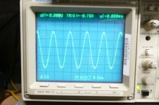
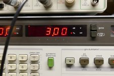
I cranked up the signal generator until the 8903A audio analyzer read about 3% THD, then entered the "Watts into 8 ohms" key sequence. The display read 14.88 watts. THD at 5 watts is 1.2%
The cathode voltage was measured at 49.6 volts for 88 mA of tube current. Total board current is 112 mA with 504 volts applied. Both halves of the 12AT7 are operating at about 10 mA though one is driving nothing in this experiment. Plate voltage measures 497 volts due to OPT DCR. This puts 447.4 volts across the tube at 88 mA, which is 39.4 watts. The output power is 14.88 watts for a total output tube efficiency of 37.7% (includes screen current). Of course the tube will still be burning up almost 40 watts when the volume is turned down, so the efficiency drops as the power output is reduced and becomes zero at idle.
I connected up the cathode feedback. This moves the ground end of the cathode bypass cap to the speaker terminal. It also moves the "power at 3% THD" up to almost 16 watts, and THD at 5 watts to 0.86%.
When a similar amp was my daily listener amp, I used the cathode feedback and a KT88 for loud or bass heavy music, but preferred a triode wired EL34 with no feedback for "female singer and a guitar" music.
Attachments
Last edited:
My first foray into SE amp used a 45 tube because I had a bunch of them. They need a 5K load so I got a pair of nice Electra Print OPT's for the 45 amp, but used them for lots of experiments that needed a good OPT. I eventually stumbled across a bunch of Transcendar "300B" OPTs on Ebay the first time that Gerry closed down Transcendar. I bought a pair, liked them, then bought all that he had and made some 300B amps. They have 4 and 8 ohm taps so they can be used at 3000 ohms or 6000 ohms with an 8 ohm load. I liked that amp at 6000 ohms for most music, but it did stuff like Pink Floyd better at 3000 ohms. I sold that amp a couple years ago. My daily listener today is an UNSET board with 26HU5's and a Toroidy OPT in it. I'll have to run some comparative tests on it when my FETSET (UNSET with no tubes) amp is finished.you both used KT88 in SE on 5k and around 500V, while I’ve tried them in UNSET at 450V or fixed/cathode biased below 400V always on 3k. Is it preferrable to make them work on 5k?
Could you please post your circuit that modifies the bias of the output tube based on the output level? I can’t find the link I saved on my old laptop.the tube will still be burning up almost 40 watts when the volume is turned down
Do you have an explanation for this? Harmonic ratios? Damping Factor? Something else?I liked that amp at 6000 ohms for most music, but it did stuff like Pink Floyd better at 3000 ohms
I have a matched quartet of EL34 (originally supposed to be used in a guitar amp) that I would like to use (one pair in parallel per channel) on a UNSET amp to get around 25 Wrms per channel. Do you have suggestions on how to parallel tubes with one single pmosfet on the cathode(s)?preferred a triode wired EL34 with no feedback for "female singer and a guitar" music
Do I remember correctly it was you explaining that triodes used as ccs to load pentodes were used in medical equipments to maximize gain? I can’t find the post.The authors of the Radiotron Design Handbook just didn't imagine how a high gm pentode and a semiconductor load could be used to bring 30+dB of local feedback to bear on their rules of thumb.
I have experimented with several methods of modifying the operating point based on needed power output over the years, but the best working system was the one published in Circuit Cellar Magazine back in 2009. This system did use a microcontroller to do the dirty work, but there are other ways of doing something similar. The system in the article only works when the output stage is a cathode or source follower. The follower is typically driven by a voltage amplifier network capable of supplying all of the VOLTAGE needed to drive the load (speaker or OPT) to full power output. This Voltage Amplifier Stage drives a follower which drives the load. The follower by its nature has a very high PSSR, so we can mess with the plate or drain voltage in real time to feed the follower just enough supply voltage to do its job at that moment in time. This is somewhat similar to how a class G or class H solid state amp works. The article is included:Could you please post your circuit that modifies the bias of the output tube based on the output level? I can’t find the link I saved on my old laptop.
Most likely, just more power output. Maybe some symbiotic interaction with the 15 inch Open Baffle speakers that I was using at the time.Do you have an explanation for this? Harmonic ratios? Damping Factor? Something else?
So far, all of my parallel experiments used separate mosfets, one for each tube. This allows for individual bias current adjustments for each tube. You might get away with directly paralleling two tubes, but I would not do it. Matched tubes generally are not that well matched, and if they are, they won't be in a year. I have also seen schemes to adjust parallel wired tubes by tweaking the screen grid voltage.Do you have suggestions on how to parallel tubes with one single pmosfet on the cathode(s)?
Look through this thread for Ross MacDonald's old patents. Triodes tend to make lousy CCS's maybe it was the other way around, a pentode CCS loading a triode?Do I remember correctly it was you explaining that triodes used as ccs to load pentodes were used in medical equipments to maximize gain? I can’t find the post.
Years ago, Glass Audio ran an article that mentioned a series of complex cathode followers called augmented cathode followers. Kind of an instrumentation amplifier, perhaps, very high performance in certain parameters.
They were pretty interesting but relatively more complicated - maybe 3-4 tubes at least two power supplies etc, but impressive performance on paper.
Has anyone here ever built/listened to one for audio?
Thanks
Murray
They were pretty interesting but relatively more complicated - maybe 3-4 tubes at least two power supplies etc, but impressive performance on paper.
Has anyone here ever built/listened to one for audio?
Thanks
Murray
- multi-volti
- Replies: 89
- Forum: Tubes / Valves
Attachments
I will trace the circuit this weekend (it still exists on its own protoboard) and post a schematic.For pentode configuration in class A the max efficency is from 28 to 43% for THD less than 10% ( Radiotron, page 562)
to be precise:
BUT View attachment 1398538 so the total plate + screen circuit efficency is lower (always Radiotron, page 562)
Which is th level of THD to say undistorted? 1% or 3%, the 10% of course is out of the limit.
With 88 there is UL (pseudotriode) configuration in that circuit so we can assume is quite similar to triode and the 25% is the max. If you don't want a distortion generator.
I mean Class A, the 88 doesn't have any curves for A2 in any possible configuration of it
Another problem in to check the THD vs frequency at different level to understand if the working point and the coupling with OT is good enough.
Who play in the real world knows that mainly at low frequency and int high region the coupling between tubes and OT is delicate to get a reasonable curve costant with the different levels at reasonable THD.
And this is the main test to follow.
please can you give me details on circuit? thx
Walter
Steve
- Home
- Amplifiers
- Tubes / Valves
- Single Ended: the pentode retaliation