@Chris Hornbeck thanks, it is indeed clear the simple ccs on a secondary or the “pull” side of the transformer, but what about the pentode used as modulated ccs? The statement of the doubled load and power was referted to that situation.
Do you mean a push-pull stage with dissimilar valves? One a triode and one a pentode? That could double the power compared to a single valve, but seems like a non-linear way to do it. Also, why? Maybe I just don't get it.
All good fortune,
Chris
All good fortune,
Chris
Hi @Chris Hornbeck ,
the basic concept is: one side of the PP is a triode (low rp) and the other side is a pentode (high rp) or a modulated CCS. The “pull” must give a specular current at every signal input with a very high rp: you double the power, but only one side has “grip” (low rp) on the speaker, like a SE.
What I don’t get is why it should see twice the impedance: the Raa will be two times the Ra, but each tube will see Ra.
I have a question trying to put different circuits and ideas together.
With this last SE in PP configuration, one side can be UNSET (low rp, non inverting) and the other normal pentode (high rp, inverting) with a voltage divider at the input.
Can the Keibert trick using a common cathode resistor of a value 1/gm (of the UNSET) be used to reduce 3rd harmonic? https://www.one-electron.com/Archiv...System Design Factors for Audio Ampifiers.pdf
Do you mean a push-pull stage with dissimilar valves? One a triode and one a pentode? That could double the power compared to a single valve, but seems like a non-linear way to do it. Also, why? Maybe I just don't get it.
All good fortune,
Chris
Back before the dawn of time, I used to build and repair guitar amps. One day a friend asked me to look at his Fender Bandmaster. It had worked good for some time but developed a crackle at high volume which got worse and occurred at lower volume levels over time. Eventually it died and blew the fuse. I opened it up to find one 6L6GC and one EL34 tube for outputs and a burnt output tube socket which had arced between pin 3 (plate) and pin 2 (heater) and shorted power supply diodes. I asked the owner about the mismatched tubes. He replied that he and one of his friends played musical tubes swapping tubes back and forth with each other in quest for a different "tone." The other guy had a Marshall. Neither amp owner used the original speaker cabinet that matched the head. My friend's cabinet had two different brand 12 inch speakers wired in series. One was 8 ohms, the other was 4. I put ceramic sockets in place of the black plastic stuff with heat shrink over pins 2 and 3 and changed the crappy Fender power supply diodes which are known to fail from power line surges. The amp was fixed. The amp DID have a unique "tone" when cranked into that oddball cabinet.Can the Keibert trick using a common cathode resistor of a value 1/gm (of the UNSET) be used to reduce 3rd harmonic?
Arcs from pin 3 to pin 2 on the output tubes, and even a few blown OPT's were not uncommon in Florida amps that had accumulated some dust, cigarette smoke, and maybe ingested a little beer over time. Add some heat and high Florida humidity and sparks happen.
This repair job gave me the crazy idea to experiment with different output tubes, and to create a push pull amp with three output tube sockets with one of the sockets switchable from one tube, the other tube, or BOTH, by switching screen voltage on or off. The third tube also had a volume control on the control grid AC drive. I let people play with these and a box full of "expendable" tubes to find their "tone." All output tubes were pentodes and mostly common "guitar amp tubes." The most popular oddball combos were two 6L6GC's and a 6V6GT or two 5881's and an EL34. These amps ran at 380 to 400 volts depending on line voltage, and used the same 6600 to 0,4,8,16 ohm "80VA" OPT that I still use today. Most of the users worked at Motorola where I worked, and had some knowledge of how electrical stuff worked, or had "techie" friends. Experimentation with preamp and output tube swapping and random mismatched loads were encouraged. Oddly only one tube blew, and it was an early Chinese KT88 which could blow even if you looked at it wrong. Even the way overvoltaged 6V6GT's survived.
The "tone" was not all that different sounding until the amp started to approach compression and clipping. That's where guitar amps often run, but not our HiFi amps. Typing this just reminded me that I have a dead guitar amp chassis on a shelf that has 5 octal sockets and 7 9 pin sockets. What kind of contraption can I make with it?
@Tubelab_com in guitarland, if you remember there’s the Simulclass series of Mesa Boogie amps that has one pair of EL34 in triode Class A and one (or more) pairs of 6L6GC in pentode class AB each amp. “Simul-Class” because the amp shares on each side of the push-pull one tube in triode class A and one (or more) tubes in pentode class AB.
Would you be interested to set the amp in push-pull with one side in UNSET and the other in pentode (or modulated CCS) with a voltage divider on g1 to have the same gain of the UNSET?
Would you be interested to set the amp in push-pull with one side in UNSET and the other in pentode (or modulated CCS) with a voltage divider on g1 to have the same gain of the UNSET?
If I remember correctly @Wavebourn uses this technique of modulated CCS in his SE amps with PP transformers.
This video seems to confirm it:
He then uses current feedback from secondary to be able to bring the Zout of his amps into negative values.
This video seems to confirm it:
He then uses current feedback from secondary to be able to bring the Zout of his amps into negative values.
I am slowly rebuilding my vacuum tube breadboarding system after 10 years of no use. Once that's done there will be lots of experiments mostly related to guitar amp use. It is pretty easy to simulate a HiFi amp in LT Spice since the usual goals are low THD with a descending harmonic profile. Guitar amps are not so easily simulated since terms like "it rocks, chugs, or growls" are not understood by the simulator and one size does not fit all.@Tubelab_com in guitarland, if you remember there’s the Simulclass series of Mesa Boogie amps that has one pair of EL34 in triode Class A and one (or more) pairs of 6L6GC in pentode class AB each amp. “Simul-Class” because the amp shares on each side of the push-pull one tube in triode class A and one (or more) tubes in pentode class AB.
Would you be interested to set the amp in push-pull with one side in UNSET and the other in pentode (or modulated CCS) with a voltage divider on g1 to have the same gain of the UNSET?
For the last several years my only working guitar amp has been the little 4 tube ultra low buck amp I designed for the Hundred Buck Amp Challenge over 10 years ago. Total parts cost, under $50 in 2011. I built that amp to show that a good sounding 4 watt tube guitar amp can be made for low $$$. Several years later I ripped it apart and started tweaking parts. At one time I had 6 or 7 pots wired into it along with a bunch of caps and DIP switches. I spent about a month optimizing it, then made a new PCB and still use the amp today.
I learned to play guitar in the early 60's. Living a bicycle ride away from the Atlantic Ocean meant that the radio always played surf music, so that's what I played. Surf music requires reverb, and a reverb tank is bigger than my whole amp, so it's time for a new one. This will be a "start from square one" approach so for now anything will be considered and the sounds i get will control which direction I go toward. Most of the FX will be included, and tubes, transistors, and IC chips are all allowed, and likely some of all three will be included.

@Tubelab_com
A friend of mine has four KT150 and proposed me two of them if I find a SE design that is simple to build.
Do you suggest the SSE?
What about an UNSET as output stage, with a 12AT7 as driver with the plate load split and bootstrapped from the source of the pmosfet of the UNSET?
Would you suggest Toroidy transformers for this specific application?
This is the amp s.e. proposed on Audioreview magazine
 .
.
It is easy to build the E88C, single triode is a beautiful tube with good gain na not so difficult to find. An alternative is 6FQ7/6CG7, very good, double tri
The Ot is HAmmond 1627se , good price for a reasonable quality.
The FB is 6dB.
This is a THD vs freq at 1 watt very good shape

The freq. response at 10 watt, some proble at high frequency but the OT has some limitation, of course

It is easy to build the E88C, single triode is a beautiful tube with good gain na not so difficult to find. An alternative is 6FQ7/6CG7, very good, double tri
The Ot is HAmmond 1627se , good price for a reasonable quality.
The FB is 6dB.
This is a THD vs freq at 1 watt very good shape
The freq. response at 10 watt, some proble at high frequency but the OT has some limitation, of course
I like it in some application as this one.I’m not a big fan of SRPP
The E88C is a good tube bu it is a single triode.
These are the curves from my Sofia
This is the freq. response of input stage
450 mV Vin, 20 Vout 0,6% of THD; -1dB at 100 kHz is enough
About grid stopper of course is possible to use, in this case I haven't met any problem.
About 0,8% THD I consider it a good value mainly because it is almost costant for a wide range of frequency that is very important; the FB is only 6 dB
And, at the end, the Hammond iron is a reasonable stuff considering the price even the value of inductance and parasitic is not so good.
This is the amp s.e. proposed on Audioreview magazine
View attachment 1403813.
It is easy to build the E88C, single triode is a beautiful tube with good gain na not so difficult to find. An alternative is 6FQ7/6CG7, very good, double tri
The Ot is HAmmond 1627se , good price for a reasonable quality.
The FB is 6dB.
This is a THD vs freq at 1 watt very good shape
===========================================================================================================
I have by mistake a lot of these E88c tubes. Is the powertube a 6L6? Is it sensible to built this circuit with a OPT without a UL connection?
The power tube is KT150 but other as 6L6 can be fine checking the specs about Pa and current.I have by mistake a lot of these E88c tubes. Is the powertube a 6L6
I think that a 6L6GC ( the strongestof this family) with 350 Vdc with 70 mA can be a good start point
Of course you can use other OT with 6L6 in triode connection so the Z of trafo can be around 2k5-3k5 kohm. It is a very good solution for me.
@Tubelab_com
I will use one of the two boards I've bought from you to apply feedback on two stages like @SpreadSpectrum Corona amp, but with UNSET configuration on both stages, bootstrapping the driver load to increase its gain.
Compared to the UNSET with local feedback only (that I like alot) I expect it not to sound SET-ish at all, but it can be an interesting switch to have on the amp to get feedback from one plate or the other and have two very different behaviours (chasing same sensitivity).
If I remember correctly @Wavebourn uses this technique of modulated CCS in his SE amps with PP transformers.
He then uses current feedback from secondary to be able to bring the Zout of his amps into negative values.
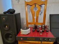
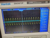
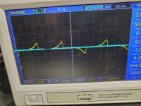
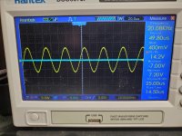
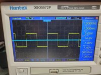
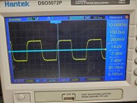
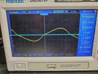
I rejected this idea for future designs. It is nice that smaller cheaper transformers can be used, but since CCS is modulated, the result is like in the middle between SE and PP. Fair SE sounds more pristine clean, soundwise. You may see attached pictures: full power 12W from 20 Hz to 20 KHz, no ringing, Edcor transformers. I am currently using it with Klipsch Chorus speakers to listen to Tidal Hi-Fi.
Feedback by current though is great, especially when I can deal it in from negative to positive to demonstrate that Damping Factor is a marketing hoax since output impedance of the amp does not damp resonances alone, it works in series with DCR of the speaker itself, so if to compensate it partly we can get a real electrical damping.
Attachments
-
 472351268_1303836383991490_5497976093960783776_n.jpg296.7 KB · Views: 80
 -
 472579379_1303836227324839_8540546474240302289_n.jpg441.7 KB · Views: 80
 -
 472554972_1303836167324845_5786999935543064275_n.jpg385.9 KB · Views: 76
 -
 472321683_1303836290658166_3869503004287495570_n.jpg396.2 KB · Views: 67
 -
 472232604_1303836493991479_7800909311539491887_n.jpg363.5 KB · Views: 77
 -
 472325618_1303836220658173_5441929413893591121_n.jpg396.9 KB · Views: 62
 -
 472676010_1303836233991505_5391914213183319402_n.jpg394 KB · Views: 77
Thank you for answering! It is indeed reasonable that even if at high impedance, the “pull” will partilly act cancelling harmonics.since CCS is modulated, the result is like in the middle between SE and PP. Fair SE sounds more pristine clean, soundwise.
Thanks again, so you suggest to go into negative output impedance to properly dampen speaker resonances.Feedback by current though is great, especially when I can deal it in from negative to positive. it works in series with DCR of the speaker itself, so if to compensate it partly we can get a real electrical damping.
Yes, the pulling current modifies natural harmonic profile that resembles dependence of harmonic on loudness in nature, so it sounds less natural, even if distortions are very low according to measurements.
In my amps output impedance can be adjusted by a single knob from minus 3.8 to plus 3.8 Ohm. I did not make it wider because over-compensation of DCR causes oscillation of woofers. I got lucky and found plenty of low ohm double pots for that, before that I used rotary switches with low ohm resistors.
Sure, negative impedance is the way to compensate DCR doing real damping. The difference between DCR+0.5 Ohm (DF=10) versus DCR+0.005 Ohm (DF=500) makes the difference only for marketing specs about "Better DF" 😉
Which ratios between harmonics can be considered natural?natural harmonic profile that resembles dependence of harmonic on loudness in nature
Like Bourns 82A2A-B24-A05/A05L ?I got lucky and found plenty of low ohm double pots
Has the variable positive current feedback a big impact in output transformer distortion?In my amps output impedance can be adjusted by a single knob from minus 3.8 to plus 3.8 Ohm.
Thanks!
@Tubelab_com @SpreadSpectrum and others
These are the two circuits:
one will have local feedback only having triode-like curves on the driver (local feedback only, anode to g1, on each stage)

the other with pentode curves on the driver (feedback from output tube anode to output tube g1 and driver g1).

How would you switch between the two feedbacks?
I think it's better to disconnect the voltage divider anode-g1-gnd on the driver when the feedback on the driver g1 is taken from the output tube, and that it is better to bring the already scaled-down signal from output tube anode to the switch, to avoid unwanted interactions.
Thank you
Roberto
These are the two circuits:
one will have local feedback only having triode-like curves on the driver (local feedback only, anode to g1, on each stage)
the other with pentode curves on the driver (feedback from output tube anode to output tube g1 and driver g1).
How would you switch between the two feedbacks?
I think it's better to disconnect the voltage divider anode-g1-gnd on the driver when the feedback on the driver g1 is taken from the output tube, and that it is better to bring the already scaled-down signal from output tube anode to the switch, to avoid unwanted interactions.
Thank you
Roberto
- Home
- Amplifiers
- Tubes / Valves
- Single Ended: the pentode retaliation