HiI connected up the cathode feedback. This moves the ground end of the cathode bypass cap to the speaker terminal. It also moves the "power at 3% THD" up to almost 16 watts, and THD at 5 watts to 0.86%.
Please can you check the Thd at 30Hz and 15 khz ( or 20kHz)?
Do you have the possibility to trace the Thd vs frequency at that level?
Thanks
Walter
No, but I can spot check enough frequencies to get the picture. Here the cathode feedback from the OPT secondary is enabled. You realize that the 15 watt level measurements are really testing the OPT and not so much the rest of the circuit. Even this 10 pound OPT doesn't like 20 Hz at 15 watts. The larger Hammond 1628SEA does better at the low frequencies but gets much worse above 10 KHz. Both of the big OPT's clean up a bit when driven by a lower impedance drive source like sweep tubes (line output) in UNSET mode where plate to grid feedback is used and the OPT is not in the feedback loop.Do you have the possibility to trace the Thd vs frequency at that level?
Frequency THD @ 1W THD @ 15 W
20 Hz 3.30% 12.39%
30 Hz 2.06% 9.53%
60 Hz 1.32% 4.41%
100 Hz 0.97% 3.49%
1 KHz 0.91% 2.97%
5 KHz 0.98% 3.10%
10 KHz 1.02% 3.88%
15 KHz 1.20% 4.51%
20 KHz 1.62% 8.09%

thx for infoNo, but I can spot check enough frequencies to get the picture
Now the question is :
can we assume an efficency much more than 25% with a circuit with a mix of sand and vacuum with FB ( I don't how much is) if the results are as listed?
Are little bit poor even at 1 watt and not good at 15 watt.
In which way we can define efficency? In my opinion is the value that give us a good medium value of THD from 20 to 20 kHz. And not the 10% (or more) of THD.
But if we are looking for the max power with 10% of THD ( almost a square wave generator) at one frequency, typical 1 kHz
Just one practical example.
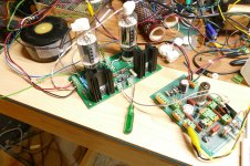
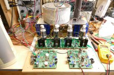
Here a little circuit built and tested live on desk because I write an article on AUdioreview in Italy around three types of OT trafo (Hammond, the Sowter and Fiat proto) involving also the 300B.
I used for Hammond ( UL connection) the KT150 working at around 400 vdc in UL, so it is same as 88. The max power is 10 watt with 2% of THD . In reality I teste it at around 500 volt where I got some more power but the purpose was another.
6 dB of FB, fixed bias.
The driver is a srpp of E88C, very good triode for me.
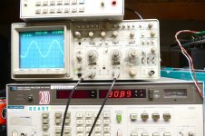
the THD at 450 mV in, 20 Vout is 0,6% THD; 44 times the gain, 33 dB around
This is the freq. response of driver
wide enough., 100 kHz at -1dB
The OT is a Hammond 1627se, it is a cheap trafo, good for this purpose.
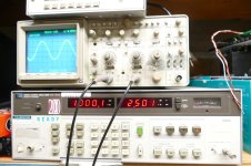
Here the freq. response at 10 wrms-8 ohm
20 Hz at -0,4 dB is fine
- 3dB at 50 khz is enough.
there is an issue at 70 Khz to 200 kHz, the quality is not high; same picture, less or more, I got testing offline the trafo.
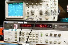
Here the THD vs Freq plot at 1 watt.
As you see the performances are much better than your number at same power and the the andament of the curve is almost perfect because the is linear a wide range of frequencies and this make a difference in terms of listening.
At 20 Hz the value is 1.7 % that is the half of your value. Same for 20 kHz.
I have to find the plot for 10 watt, maybe is in another pc; the plots are from 2017.
And I am using a cheap trafo; I have on hand other beautiful stuff, the last one a Nanocristalline proto, the results are much better( tested with 300B)
My opinion at the end:
These results are fine because the circuit is simple, two stage ( I think if you use the ECC81. p.e. probably you get also a good results so you save space), cheap trafo, low THD with low FB factor and, mainly, less complicated from other implementation
Walter
Your results are different than mine, but the amp designs are different. Your feedback loop includes the driver and output tube, while mine only encloses the output tube. My amp design dates back to 2005 and I have not changed it at all except for a modification in 2010 to improve rectifier tube reliability when the three major new production tube makers were turning out some poor quality 5AR4's. I tried global feedback to the driver cathode in the early days and it did improve the measured performance, but I and most others liked the output tube only connection sound wise. No feedback at all was preferred to the global connection. The SSE has proved to be a well regarded "simple" amp design, which was the original request that created it. The test results would likely be quite a bit different with a different OPT, especially one with a 2500 ohm primary.
I have a new design in the works that also uses only local feedback. I will post some numbers with it when I have time to remove the SSE and set it up.
In a real music listening session the average output power is below 1 watt, often well below 1 watt with the typical high efficiency FR speakers often used with an SE amp. 10 or 15 watts will only be seen on loud musical peaks or transients where a little distortion will often go unnoticed.
I have a new design in the works that also uses only local feedback. I will post some numbers with it when I have time to remove the SSE and set it up.
The 12AT7 that is used in the SSE is an ECC81. I found a pair of 1.5 K ohm Toroidy OPT's. I am going to connect the 4 ohm tap to my 8 ohm load to get a 3000 ohm load on the KT88. I'm guessing the results will be a little less poor. The clipping with the 5K OPT was not symmetrical, but I did not attempt to tweak the bias current to fix it.I think if you use the ECC81. p.e. probably you get also a good results
In a real music listening session the average output power is below 1 watt, often well below 1 watt with the typical high efficiency FR speakers often used with an SE amp. 10 or 15 watts will only be seen on loud musical peaks or transients where a little distortion will often go unnoticed.
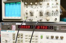
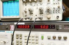
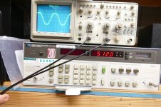
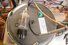
I wired the Toroidy TTG-KT88PSE into the SSE board. This OPT is designed for a parallel pair of KT88's in SE. I only ran one KT88 so I connected the 8 ohm load to the 4 ohm tap to reflect a 3000 ohm load to the KT88. Running this combo on 500+ volts would not be a good idea since excessive tube current would be needed to get a decent match. I played with the cathode resistor value and the B+ voltage to get symmetrical clipping at 16 watts of output, testing at 1 KHz. I wound up with a parallel combination of resistors totalling 375 ohms in the cathode circuit. The plate voltage was 442 volts and the cathode voltage was 40.2 volts. This equals 107 mA through the tube burning 43 watts in plate and screen. This is a bit hotter than where I was with the 500 volt setup, and produced a bit more power as the 3% THD point was 16.34 watts compared to the 14.88 watts I had on 500 volts. I did not try any feedback, as I didn't have much test time. The test data was much better. I forgot to do 15KHz. I should have tried a parallel pair of KT88's since that's what these OPT's were designed for but I have a blown cathode resistor and likely bad cap in the board and ran out of time. I may try it at a later date, but I need to make some comparative tests with a new amp design that should do much better.
Frequency THD @ 1W THD @ 10 W THD @ 15 W
20 Hz 1.24% 13.09% 22.3%
30 Hz 1.16% 4.72% 11.2%
60 Hz 0.751% 2.41% 3.68%
100 Hz 0.60% 2.02% 2.81
1 KHz 0.52% 1.71% 2.36%
5 KHz 0.524% 1.69% 2.22%
10 KHz 0.527% 1.62% 2.08
20 KHz 0.747% 1.36% 1.96%
Frequency THD @ 1W THD @ 10 W THD @ 15 W
20 Hz 1.24% 13.09% 22.3%
30 Hz 1.16% 4.72% 11.2%
60 Hz 0.751% 2.41% 3.68%
100 Hz 0.60% 2.02% 2.81
1 KHz 0.52% 1.71% 2.36%
5 KHz 0.524% 1.69% 2.22%
10 KHz 0.527% 1.62% 2.08
20 KHz 0.747% 1.36% 1.96%
HiIn a real music listening session the average output power is below 1 watt, often well below 1 watt with the typical high efficiency FR speakers often used with an SE amp. 10 or 15 watts will only be seen on loud musical peaks or transients where a little distortion will often go unnoticed.
I agree but we have to consider that in a real load, p.e. a bass reflex high efficency, in the low mid region (whre the music energy is great) there are two peaks around 30 to 100 Hz and in some case the andament of modulus has great rilevance
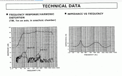
Thsi is an example (just to speak) form Audioreview magazine.
90dB of efficency
take the curve blu ( modulus) at around 70 Hz, there is a peak . From 40 to 70 the modulus increasing ( so no problem at all) but after goes down quickly (from 30 to 5 ohm in 30 Hz range), what do you think will happen is you circuit doesn't have a low distortion vs freq. at different power? And, of course, the quality of OT must be fine.
Same approach on high frequency but less problem in this case
Then, you wrote that in some circut as proposed the gain at open loop is great so it is possible to put around 30 of FB.
But if you look at the phase (red line) you have a great variation also in a narrow range of frequency and in some cases, with peaks, I don't know what happen.
My approach is alway get the best results at open loop the apply (in case) some FB; 6 dB is nothing.
With 300B no FB are applied; normally I use a single secondary fixed at 5 ohm with greater ratio to reach also a reasonable DF even is the FB is not used
The second set of test you sent seems to be almost fine but always some trouble at low frequency still exist.
The last proto of OT
Hi
in attach the first proto of 300B OT with nano
It is 3k primary
5 ohm secondary (single)
Around 40H -100Hz but some adj with gap will be possible.
At the end it will be potted.
The first test are almost fine.

The Freq. answer; there is a little step at 50kHz, but it will be fixed
Zs are 700 ohm (blu) and 1 kohm (red)
At thr moment out of the power stage that will be ready soon

The phase
cancelled due an error
in attach the first proto of 300B OT with nano
It is 3k primary
5 ohm secondary (single)
Around 40H -100Hz but some adj with gap will be possible.
At the end it will be potted.
The first test are almost fine.
The Freq. answer; there is a little step at 50kHz, but it will be fixed
Zs are 700 ohm (blu) and 1 kohm (red)
At thr moment out of the power stage that will be ready soon
The phase
cancelled due an error
- waltube
- Replies: 144
- Forum: Tubes / Valves
Walter
Thanks George, that's 38% efficiency in UL configuration.the tube burning 43 watts in plate and screen. The 3% THD point was 16.34 watts
I don't know why there's still need to prove that we can go above 25% in class A 2024, but that's it...
It was not Tubelab_com, it was SpreadSpectrum using another approach. You are always confused.Then, you wrote that in some circut as proposed the gain at open loop is great so it is possible to put around 30 of FB.
You can read the link I posted before and see how flat the response of SpreadSpectrum amp is. This way you can learn.I don't know what happen.
Like here where you have not even noticed the 50Hz hum is as high as the second harmonic, as jhstewart9 showed you few posts later (and you still haven't understood)?My approach is alway get the best results
Link to post
Or like here where you claimed you are testing the transformers for a new company, and you don't even noticed you reversed the phase while testing?
Link to post
Or here where you claimed a pentode cannot have a DF lower than 1 unless you apply alot of feedback?
Link to post
Or like in this thread, where you claimed you get 10Wrms out of a 60W KT150 tube, and so you are right that the maximum class A efficiency is 25%?
Now you are trying to mess with output transformer limits to say that you are still right, even if everyone (theory included) is proving you are wrong.
I'm asking the moderators to stop you from creating mess without any useful purpose.
One could write a book on the interaction between a vacuum tube (or any lowish DF) amp and a speaker system. The interaction between the two is complex and not always easy to predict when the amp has a non zero output impedance and the speaker has multiple impedance bumps. The usual graphs of impedance and phase are informative, but do not address the entire picture as they are all steady state graphs done with a single frequency swept sine wave at a relatively low power level. We do not listen to single frequency sine waves often. Music is complex and often contains program material that asks the speaker system to do multiple conflicting things at once.
A moving speaker cone (mass) is mechanically coupled to a coil of wire in a magnetic field which can turn electrical energy into mechanical cone motion but can also turn cone motion into electrical energy. What do you think the instantaneous impedance of a large speaker cone is when the cone is moving in one direction at a low frequency say from a bass guitar and a large kick drum transient tries to instantly reverse its direction, the direction of the air inside, and in front of the cabinet. I spent a lot of time with a drum set, a music keyboard, a bass guitar and a Teac 4 track R to R tape recorder creating test tracks for some experiments to measure this. I tinkered with both sealed and ported cabinets. After nearly a year of experimenting, and launching stuff from speaker cabinet ports, I had convinced myself that in some cases the speaker impedance can appear negative for several milliseconds. I also learned not to put a Shure SM-57 INSIDE the bass drum! The further I dug, the more complicated things got, so I wisely gave up my quest.
One could argue and dispute the merits of two fairly similar amp circuits forever with is no clear results, since there are too many uncontrollable variables. For any controlled experiment to be useful, only variable should be changed at a time to observe its contribution to the experiment. In between the two sets of data I posted, I changed three things, the OPT, the tube's operating point, and the removal of local feedback to the output tube's cathode.
My personal SSE amp was used as the monitors on my PC which was used for audio recording and music generation via a DAW, Ableton Live or FL Studio. I also tinker with various software music synthesizers and software guitar amp modelers. I bought a pair of Yanaha NS-10M Studio monitors in 1989 and switched to digital recording in the early 90's when the 16 bit Media Vision Pro Audio Spectrum sound card came out. The PAS16 has been replaced with a 48 KHz, 24 bit Focusrite interface, and the SSE was replaced with an UNSET tube amp of my own design last year, but the NS10M's still remain, along with whatever DIY cabinets I happen to be tinkering with at the time.
The NS10M's have limited output below 75 Hz, so the large distortion at 20 Hz does not matter in MY setup. The low frequencies are handled by a powered subwoofer. Everyone's setup is different, but many who use moderately powered SE amps don't have response to 20 Hz either.
I have a limited selection of OPT's that I use for experiments. I'm not going to buy any expensive OPT's because my 72 year old ears are not like they were when I was young, and the only speakers that I have owned for 35 years are the NS10's, which are my reference standard, so the expense of fancy OPT's would not be warranted.
Users of this forum still seem to be interested in what I post, so I will keep posting the results of my experiments, but I will not debate their merits since I would rather fry some parts in the name of science.
Attachments
Will it be enough just one? I’m thinking about how many nuances instrument amps have, how many controls have been implemented in instrument and hi-fi amplification, how many debates about DF over the years.One could write a book on the interaction between a vacuum tube (or any lowish DF) amp and a speaker system.
IMHO a good class D subwoofer can do better than a tube SE in the first octave. Above that, in the last years I’m enjoying fullrangers more and more (they go reasonably down to 30 to 40 Hz).many who use moderately powered SE amps don't have response to 20 Hz either.
Please do!Users of this forum still seem to be interested in what I post, so I will keep posting the results of my experiments
It might be worth going back to discussing the circuit in post #251 before we got derailed trying to prove that a properly-designed SE KT88 can put out 15W.
The circuit is pretty similar to things that I have tried in the past. The two main differences are:
1. UL output tube configuration. My gut tells me that this would increase total distortion rather than decrease it, but I could be wrong. If I were building this, I'd be prepared to try it both ways and see which one does better.
2. The pentode load. This load will provide a high impedance at AC but a low impedance at DC. This will stabilize the pentode idle plate voltage. However, idle current will be allowed to drift. My gut tells me that this will be overall a more stable system than the CCS loads I have been using, but you'd still want to keep an eye on it in testing. I'd also be curious to see how high the AC impedance of the gyrator load is compared to the cascode CCS. Do you give up some gain with high-gm pentodes by going to the gyrator load?
I noticed that with UNSET. I noticed once an improvement when UL percentage and UNSET shared the same percentage (Vg2-k=const), but at the end pentode connection showed best overall results.UL output tube configuration. My gut tells me that this would increase total distortion rather than decrease it
With CFB (connecting the cathode of the KT88 to the 8 Ohm tap) distortion drops even further, and output transformer performs better, but we are in the 10-20 Ohm rp for the output tube. What can be heard is the output transformer and speaker distortion.
I would prefer George to answer, as he has way more experience on it. Gain is excessive without your feedback, as you know. It doesn’t sound like a classical SE amp (while UNSET does), but it is something very interesting.I'd also be curious to see how high the AC impedance of the gyrator load is compared to the cascode CCS. Do you give up some gain with high-gm pentodes by going to the gyrator load?
Which speaker do you use usually with this amp?
Today's experiment used a circuit similar to post #251 except for the feedback connection. I use the P ch mosfet on the cathode as the signal input and apply local negative feedback to G1 with a simple two resistor voltage divider from plate to ground. The gyrator load on the pentode gives a big bunch of gain due to a very light AC load on the plate. This gain is dialed back with plate to grid feedback to the desired value. I bit of tweaking can reveal plenty of gain with nearly zero distortion.
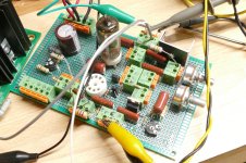
Step one was to dig out my breadboard and fire it up. Before the "test it from DC to light" requests are asked, I designed this for use in a guitar amp with a gain pot so that the gain could be varied from about 10 V/V to about 1000 V/V. I also used small value coupling caps to roll off the low end since a guitar only goes down to 82.4 Hz. The gain at 20 Hz is negative. Unfortunately changing the caps would not be easy on this breadboard. There will however be another iteration in the future. Why? The driver stage can put out 50 volts RMS at under 0.1% THD. The residual THD on the audio generator is 0.04%.
Step one was to dig out my breadboard and fire it up. Before the "test it from DC to light" requests are asked, I designed this for use in a guitar amp with a gain pot so that the gain could be varied from about 10 V/V to about 1000 V/V. I also used small value coupling caps to roll off the low end since a guitar only goes down to 82.4 Hz. The gain at 20 Hz is negative. Unfortunately changing the caps would not be easy on this breadboard. There will however be another iteration in the future. Why? The driver stage can put out 50 volts RMS at under 0.1% THD. The residual THD on the audio generator is 0.04%.
Attachments
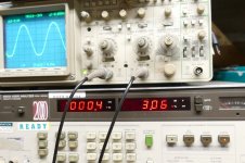
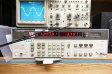
Step two of the experiment gets the output of this driver fed into an UNSET OUTPUT BOARD with both channels wired in parallel. A pair of fat TV sweep tubes were installed, feeding the same Toroidy OPT that I used yesterday with the KT88's. and the phasers were set on STUN (3000 ohm load 460 volts of B+). I turned up the drive until I saw the power pass 30 watts. THD was 2.5%. Dialing it back to 20 watts yields a THD of 0.7% with 0.68% at 10 watts. The totally sloppy unshielded clip lead ratsnest wiring scheme is responsible for some 60 Hz hum that produces a distortion floor of 0.6%.
Attachments
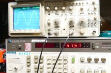
Step three, phasers on KILL (change to 1500 ohm load, crank B+ to 480 volts. It's gonna go or its gonna blow.......It goes! To the tune of 57 watts at 3.06% THD with a bit of clipping on the bottom of the sine wave. Dialing back the drive to get 50 watts out yields 1.8% THD.
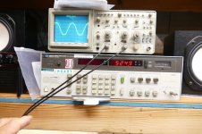
The 380 volt supply only fed the OPT. The plate current at 50 watts was 303 mA for 115 watts of DC input. Thus yielded 50 watts of audio power for about 43 % plate efficiency. This burns 32.5 watts per tube which is in spec. That's not the problem. The amp will have to eat all 115 watts at idle or low volume which would make the tubes quite unhappy. Want a real 50 watt SE amp? You would need three or four output tubes in parallel. If I was going to use 4 tubes, I would make a push pull amp that does 400 to 500 watts with the same tubes in the same configuration.
The 380 volt supply only fed the OPT. The plate current at 50 watts was 303 mA for 115 watts of DC input. Thus yielded 50 watts of audio power for about 43 % plate efficiency. This burns 32.5 watts per tube which is in spec. That's not the problem. The amp will have to eat all 115 watts at idle or low volume which would make the tubes quite unhappy. Want a real 50 watt SE amp? You would need three or four output tubes in parallel. If I was going to use 4 tubes, I would make a push pull amp that does 400 to 500 watts with the same tubes in the same configuration.
Attachments

At which current you set the driver to drive two pmosfet in parallel up to 20 kHz? Something around 10 mA?Step two of the experiment gets the output of this driver fed into an UNSET OUTPUT BOARD with both channels wired in parallel.
Do you know the DF in this configuration? I don’t ask you the DC-to-light performance because I know that output transformer and at 20 Hz it struggles with 1/3rd of that power.Step three, phasers on KILL (change to 1500 ohm load, crank B+ to 480 volts. To the tune of 57 watts at 3.06% THD
What about the phase inverter? Driving the cathode with a source follower, you can’t use the LTP configuration. Would you use the UNSET for the output stage only?If I was going to use 4 tubes, I would make a push pull amp that does 400 to 500 watts with the same tubes in the same configuration.
Thanks!
I was looking at @smoking-amp posts to find the statement about the ccs loded pentode used in medical stuff in the ‘50s and ask more details, and I’ve found this interesting post (and following) dated 2010:
I understand the PP output transformer balancing the current on both sides, but I don’t get why the load and power are doubled for the triode (that could be of course an UNSET). Can someone explain the point to me please?
I think what Anatolyi (Wavebourn) is mentioning are the modulated current source schemes. These can get 50% theoretical efficiency just like an inductance loaded SE. These approaches are of the type I refer to as P-P schemes to give SE sound. Numerous variations around. An interesting area. The simplest is to just build a P-P amp (class A mode) with a triode on one side and a pentode on the other (it's grid is driven still, not a CCS), balance the DC idle current and balance the effective gm's (adjustable grid drive for the pentode). The triode calls the shots as far as voltage goes (SE...
I understand the PP output transformer balancing the current on both sides, but I don’t get why the load and power are doubled for the triode (that could be of course an UNSET). Can someone explain the point to me please?
The famous Klimo Beltaine use a p-p trafo with 300B in one side and EL34 in other side to compensate the bias current.
It was a well considered amp and not cheaper
Walter
It was a well considered amp and not cheaper
Walter
That test experiment already happened, and the UNSET output boards were driven directly from the plates of the 6CG7 LTP in one of my Universal Driver Boards. Here one driver board is driving two UNSET boards each board has its two channels wired in parallel. The Vanderveen OPT is rated for "400 watts @ 20 Hz." It will easily do 500 watts but DC balance must be maintained. The point of minimum distortion is not at exactly matching currents, but at a few mA offset.What about the phase inverter? Driving the cathode with a source follower, you can’t use the LTP configuration. Would you use the UNSET for the output stage only?
THD is 0.817% @ 350 watts and 3.79% @ 512 watts. Clipping becomes evident at 525 watts.
The UD board uses one LTP DC coupled to a second LTP to provide ample gain and matched signals of opposing phase. Any of the typical twin triode tubes can be used, but here both tubes are 6CG7's. The board also contains a pair of mosfet followers on the output for driving complex loads, but they were bypassed for this test. Each UNSET Output Board has a P-fet in the cathode of each tube. Since they run as followers the only load the driver sees is the Crss of two paralleled fets. The FQP9P25's used are 27 pF each.
This is a class AB amp with idle currents well into the safe zone for the output tubes. Maximum dissipation ratings would be exceeded if the amp would be operated continuously at about 2/3 of full power output, and maximum screen grid dissipation would be exceeded if the amp were to be run above 500 watts continuously. Four output tubes per channel would not be an issue in a normal listening environment, if there is such a thing with a 500 WPC amp, but 6 tubes should be used if someone was trying to shake a whole apartment complex with Smoke on the Water at 11 on the Richter Scale.........I used transistors and a pair of bass guitar cabinets each containing 4 X 12 inch speakers to silence the Disco Queen in 1975.
Attachments


That thread could easily be mistaken (lots of the early parts are now missing, because not on diyAudio) to mean that somehow efficiency could be improved (not true; it's halved) or that somehow idling magnetism could somehow be zero'd without putting exactly as many amp-turns into the transformer, from a high impedance current source, as the active device. The current source itself will need to have a voltage swing overhead (burden) appropriate to signal voltage at its transformer tap, further reducing efficiency. Second Law is strict.I understand the PP output transformer balancing the current on both sides, but I don’t get why the load and power are doubled for the triode (that could be of course an UNSET). Can someone explain the point to me please?
All good fortune,
Chris
- Home
- Amplifiers
- Tubes / Valves
- Single Ended: the pentode retaliation