Isn't it difficult to believe that an amplifier, out in the wild, would be stable with so much positive feedback? Spice models are interesting, but lack common sense. Ancient Zen koan: What is the difference between an amplifier and an oscillator?
All good fortune,
Chris
All good fortune,
Chris
@Chris Hornbeck the japanese site says that the amp is stable until Zout = 1, below that not so much, but there was still space for layout improvements.
This seems also a reasonable "area" for bandwidth, but in any case we have always the possibility to add gnfb.
This seems also a reasonable "area" for bandwidth, but in any case we have always the possibility to add gnfb.
Bandwidth improves if we configure the output tube in pentode, without UL: all parameters kept equal, we reach -1 dB at 21 kHz and -3 dB at around 40 kHz.
Distortion improves too, as these are now the results at 1 Wrms with 8 Ohm load:
and with the same input voltage 360 mVp (255 mVrms) but 12 Ohm to calculate Zout = 6:
And this is the simulation with 1.1Vp at the input (778 Vrms) and 9 Wrms:
Distortion improves too, as these are now the results at 1 Wrms with 8 Ohm load:
Code:
Harmonic    Frequency     Fourier     Normalized     Phase      Normalized
 Number       [Hz]       Component     Component    [degree]    Phase [deg]
    1       1.000e+03    3.996e+00    1.000e+00        0.06°        0.00°
    2       2.000e+03    1.364e-02    3.414e-03       91.42°       91.35°
    3       3.000e+03    9.175e-04    2.296e-04       16.85°       16.79°
    4       4.000e+03    2.172e-04    5.436e-05     -126.23°     -126.30°
    5       5.000e+03    8.448e-05    2.114e-05     -175.38°     -175.44°
    6       6.000e+03    5.548e-05    1.388e-05      177.94°      177.88°
    7       7.000e+03    4.794e-05    1.200e-05     -179.97°     -180.03°
    8       8.000e+03    4.233e-05    1.059e-05     -179.79°     -179.85°
    9       9.000e+03    3.762e-05    9.415e-06     -179.83°     -179.89°
Total Harmonic Distortion: 0.342266%(0.342276%)
and with the same input voltage 360 mVp (255 mVrms) but 12 Ohm to calculate Zout = 6:
Code:
Harmonic    Frequency     Fourier     Normalized     Phase      Normalized
 Number       [Hz]       Component     Component    [degree]    Phase [deg]
    1       1.000e+03    4.190e+00    1.000e+00       -0.20°        0.00°
    2       2.000e+03    7.645e-03    1.825e-03       95.38°       95.58°
    3       3.000e+03    2.256e-04    5.385e-05       49.17°       49.36°
    4       4.000e+03    1.272e-04    3.037e-05     -168.79°     -168.59°
    5       5.000e+03    7.962e-05    1.900e-05     -175.53°     -175.34°
    6       6.000e+03    6.031e-05    1.439e-05     -179.24°     -179.04°
    7       7.000e+03    5.230e-05    1.248e-05      179.99°      180.19°
    8       8.000e+03    4.596e-05    1.097e-05     -179.89°     -179.70°
    9       9.000e+03    4.084e-05    9.748e-06     -179.85°     -179.65°
Total Harmonic Distortion: 0.182582%(0.182602%)
And this is the simulation with 1.1Vp at the input (778 Vrms) and 9 Wrms:
Code:
Harmonic    Frequency     Fourier     Normalized     Phase      Normalized
 Number       [Hz]       Component     Component    [degree]    Phase [deg]
    1       1.000e+03    1.196e+01    1.000e+00        0.06°        0.00°
    2       2.000e+03    2.605e-01    2.178e-02       88.37°       88.31°
    3       3.000e+03    1.424e-01    1.190e-02        7.30°        7.24°
    4       4.000e+03    5.482e-02    4.583e-03     -102.61°     -102.67°
    5       5.000e+03    6.094e-02    5.095e-03     -173.12°     -173.18°
    6       6.000e+03    1.703e-02    1.424e-03       76.30°       76.24°
    7       7.000e+03    2.612e-02    2.183e-03        4.84°        4.79°
    8       8.000e+03    8.096e-03    6.769e-04     -101.33°     -101.39°
    9       9.000e+03    1.156e-02    9.662e-04     -178.95°     -179.01°
Total Harmonic Distortion: 2.590735%(2.591547%)
Last edited:

So this could be an oversimplified circuit on the edge of Zout = 1 Ohm:

Bandwidth is -1dB at 20 kHz, and with an higher load for the driver, the overall performance is better:
So this the simulation at 1 Wrms and 8 Ohm load.
under 12 Ohm load to check DF = 8:
And here again at 9 Wrms:
Bandwidth is -1dB at 20 kHz, and with an higher load for the driver, the overall performance is better:
So this the simulation at 1 Wrms and 8 Ohm load.
Code:
Harmonic    Frequency     Fourier     Normalized     Phase      Normalized
 Number       [Hz]       Component     Component    [degree]    Phase [deg]
    1       1.000e+03    4.062e+00    1.000e+00       -1.57°        0.00°
    2       2.000e+03    1.284e-02    3.160e-03       82.45°       84.02°
    3       3.000e+03    6.012e-04    1.480e-04       16.44°       18.01°
    4       4.000e+03    1.368e-04    3.367e-05      -89.37°      -87.80°
    5       5.000e+03    1.951e-05    4.802e-06      -12.23°      -10.65°
    6       6.000e+03    2.726e-05    6.710e-06        4.20°        5.77°
    7       7.000e+03    2.274e-05    5.598e-06        0.63°        2.20°
    8       8.000e+03    1.956e-05    4.815e-06        0.24°        1.81°
    9       9.000e+03    1.741e-05    4.286e-06        0.25°        1.82°
Total Harmonic Distortion: 0.316371%(0.316373%)
under 12 Ohm load to check DF = 8:
Code:
Harmonic    Frequency     Fourier     Normalized     Phase      Normalized
 Number       [Hz]       Component     Component    [degree]    Phase [deg]
    1       1.000e+03    4.212e+00    1.000e+00       -1.52°        0.00°
    2       2.000e+03    9.163e-03    2.176e-03       81.94°       83.46°
    3       3.000e+03    1.574e-04    3.737e-05       95.15°       96.67°
    4       4.000e+03    3.209e-05    7.620e-06     -134.06°     -132.54°
    5       5.000e+03    4.818e-06    1.144e-06     -123.23°     -121.71°
    6       6.000e+03    2.072e-06    4.920e-07      -15.44°      -13.92°
    7       7.000e+03    1.314e-06    3.120e-07        5.51°        7.03°
    8       8.000e+03    9.693e-07    2.301e-07        2.32°        3.84°
    9       9.000e+03    8.774e-07    2.083e-07        0.34°        1.86°
Total Harmonic Distortion: 0.217603%(0.217601%)
And here again at 9 Wrms:
Code:
Harmonic    Frequency     Fourier     Normalized     Phase      Normalized
 Number       [Hz]       Component     Component    [degree]    Phase [deg]
    1       1.000e+03    1.206e+01    1.000e+00       -1.62°        0.00°
    2       2.000e+03    2.016e-01    1.672e-02       80.32°       81.94°
    3       3.000e+03    9.250e-02    7.672e-03        9.64°       11.26°
    4       4.000e+03    3.928e-02    3.257e-03     -117.15°     -115.53°
    5       5.000e+03    4.499e-02    3.731e-03     -171.56°     -169.94°
    6       6.000e+03    1.371e-02    1.137e-03       45.99°       47.60°
    7       7.000e+03    2.234e-02    1.853e-03        3.42°        5.04°
    8       8.000e+03    6.130e-03    5.084e-04     -131.00°     -129.38°
    9       9.000e+03    1.069e-02    8.867e-04      174.55°      176.16°
Total Harmonic Distortion: 1.920199%(1.921309%)@jhstewart9 sorry, I heavily hijacked the thread with this circuit.
Someone knows how to move those posts in the my "pentode retaliation" thread ( https://www.diyaudio.com/community/threads/single-ended-the-pentode-retaliation.373257/ )? It is more in topic there.
Someone knows how to move those posts in the my "pentode retaliation" thread ( https://www.diyaudio.com/community/threads/single-ended-the-pentode-retaliation.373257/ )? It is more in topic there.
For these tests the OPT model has been corrected. And parasitic capacitance's included for the pentode model of the EL34.
Freq response looks much better, the top end at -3db is now ~48 KHz.
Freq response looks much better, the top end at -3db is now ~48 KHz.
Attachments

Find the post where your hijack started.@jhstewart9 sorry, I heavily hijacked the thread with this circuit.
Someone knows how to move those posts in the my "pentode retaliation" thread...? It is more in topic there.
Click the "(!)Report" link under that post. Say that you would like a moderator to move some posts. Be clear! Move posts in? Move posts in to?
Seems like a promising and very simple design.
There may be some over-simplification in the present tube design. Normally the "error-correction" scheme is used in unity gain SS output stages, so one only needs to derive the output-input to get the error component. This tube design is using the front end gain stage to inject the correction, so one needs not only scaled output-input derived accurately, but also a scaling factor to set the error injection to 1/gain. The 6.8K/1.5K resistors and inverted U2 gain nominally set those, but other tubes will require adjustment here. Then there is the peak plate voltage problem for U2, which George mentioned. Having the gain stage in the correction loop also means that any gain drift by either tube will affect the correction accuracy. Not usually the kind of issues one wants for a set and forget Amp, but for DIY (with some test equip. ) may be just fine. The inverted tube operation makes it interesting, and puts the design in "tube emulation" territory with a few minor changes.
Last edited:
Then there is the peak plate voltage problem for U2, which George mentioned.
May be possible with a power tube like a 6V6 pentode connected for higher gain ?
This amp and your UNSET will both go with a pair of full range horn loaded speakers (FHXL and Silbury) with a very flat impedance vs frequency plot.I also blew up a couple 12AU7's and one 12BH7 before abandoning this experiment. Both of those tubes are rated for TV vertical sweep duty allowing a peak positive plate voltage of 1200 or 1500 volts.
Will it make it acceptable for 12AU7?
Hi George, what safety margin do you usually consider for the current of the driver vs the needed to guarantee the right slew rate?The driver must be capable of driving this directly without distortion or slew rate limiting.
To get the minimum THD and max Damping factor to coincide better.
Lift bottom of R5 and C2 above ground connection by 10 Ohms. Then take a 100K pot, U5, from top of 10 Ohm resistor to U1 cathode. Adjust U4 for minimum THD. Adjust U5 for almost max damping. (just want to cancel OT primary resistance in order to remove OT magnetizing distortion)
I've played a bit around the suggestions that @smoking-amp and @Tubelab_com gave and I came out with the following circuit.
To overcome the issue underlined by @Tubelab_com about the max plate voltage of the 12AT7, I connected the anode of the tube to the UL tap instead of the anode of the EL34. This way the swing will only be 40% of the total anode swing, and it will stay way below 550V peak. Also considering that I'll use mostly horn loaded fullrange speakers with a quite flat 8 Ohm load.
I have then connected the feedback as per @smoking-amp and played with values a bit to get a reasonable THD and Rout, keeping a strong 2nd harmonic dominance. I'm sure it can be largely optimized further more.
Now the amp gives 1 Wrms with the following THD:
Code:
Harmonic    Frequency     Fourier     Normalized     Phase      Normalized
 Number       [Hz]       Component     Component    [degree]    Phase [deg]
    1       1.000e+03    4.003e+00    1.000e+00       -0.67°        0.00°
    2       2.000e+03    3.889e-02    9.715e-03       86.95°       87.61°
    3       3.000e+03    2.919e-03    7.293e-04       -2.26°       -1.59°
    4       4.000e+03    2.777e-04    6.937e-05      -90.44°      -89.77°
    5       5.000e+03    1.382e-05    3.452e-06      167.46°      168.13°
    6       6.000e+03    1.566e-05    3.912e-06       11.72°       12.39°
    7       7.000e+03    1.325e-05    3.310e-06        2.36°        3.03°
    8       8.000e+03    1.122e-05    2.804e-06        2.09°        2.76°
    9       9.000e+03    9.974e-06    2.492e-06        2.07°        2.74°
Total Harmonic Distortion: 0.974306%(0.974306%)
and 10 Wrms with the following THD:
Code:
Harmonic    Frequency     Fourier     Normalized     Phase      Normalized
 Number       [Hz]       Component     Component    [degree]    Phase [deg]
    1       1.000e+03    1.275e+01    1.000e+00       -0.66°        0.00°
    2       2.000e+03    5.479e-01    4.297e-02       86.90°       87.56°
    3       3.000e+03    2.204e-01    1.729e-02       -1.74°       -1.08°
    4       4.000e+03    4.377e-02    3.432e-03      -96.02°      -95.36°
    5       5.000e+03    4.734e-02    3.713e-03      177.55°      178.21°
    6       6.000e+03    9.908e-04    7.770e-05      -22.90°      -22.24°
    7       7.000e+03    1.455e-02    1.141e-03       -4.20°       -3.54°
    8       8.000e+03    3.987e-03    3.126e-04       78.14°       78.80°
    9       9.000e+03    6.001e-03    4.706e-04      170.59°      171.25°
Total Harmonic Distortion: 4.660536%(4.661305%)
Attachments
I report here the last development of the circuit.
The input stage is a 12AT7 CCS loaded going to an EL34 in UNSET configuration.
On the same voltage divider that gives feedback to EL34's g1 there's a trimmer to send the scaled down plate signal to J1 (U440).
On the gate of J1 I inject also the input signal, and the trimmer must be set in order to cancel the input signal and obtain only the distortion at J1's gate.
So the 12AT7's cathode will not receive the full signal as feedback, but only the distortion, when there's any.
This way when the amp "has no distortion", the amp has no feedback at all. This allows to have very low output impedances with just two gain stages.
This is the feedback signal at 1 Wrms:

I will try it with something I already have: a bad output transformer ( https://www.hammfg.com/files/parts/pdf/125DSE.pdf ) to see how it will perform in worst conditions.
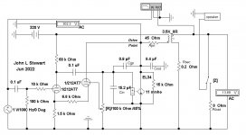
This is the circuit (the PMOS that drives the EL34 in reality will be a FQPF9P25):

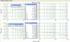
This is the simulated bandwidth:

This is the simulated THD at 1 Wrms:
The Rout of the circuit is 0.8 Ohm with all feedbacks, but it simulates well also without the njfet feedback, obtaining a Zout around 3 Ohm and "better harmonics" when going above nominal power, that is 10 Wrms.
@smoking-amp J1 could even be an OPAMP like you used, I'd just use it as a differential amplifier, considering the input signal as the "noise" to be eliminated in the nfb loop.
In attachment the LTSpice file to let others play with it.
The input stage is a 12AT7 CCS loaded going to an EL34 in UNSET configuration.
On the same voltage divider that gives feedback to EL34's g1 there's a trimmer to send the scaled down plate signal to J1 (U440).
On the gate of J1 I inject also the input signal, and the trimmer must be set in order to cancel the input signal and obtain only the distortion at J1's gate.
So the 12AT7's cathode will not receive the full signal as feedback, but only the distortion, when there's any.
This way when the amp "has no distortion", the amp has no feedback at all. This allows to have very low output impedances with just two gain stages.
This is the feedback signal at 1 Wrms:
I will try it with something I already have: a bad output transformer ( https://www.hammfg.com/files/parts/pdf/125DSE.pdf ) to see how it will perform in worst conditions.
This is the circuit (the PMOS that drives the EL34 in reality will be a FQPF9P25):
This is the simulated bandwidth:
This is the simulated THD at 1 Wrms:
Code:
Harmonic    Frequency     Fourier     Normalized     Phase      Normalized
 Number       [Hz]       Component     Component    [degree]    Phase [deg]
    1       1.000e+03    3.954e+00    1.000e+00       -0.49°        0.00°
    2       2.000e+03    3.934e-03    9.948e-04      -92.65°      -92.16°
    3       3.000e+03    8.448e-04    2.137e-04        1.37°        1.85°
    4       4.000e+03    3.759e-05    9.506e-06       85.08°       85.57°
    5       5.000e+03    7.654e-06    1.936e-06     -177.05°     -176.57°
    6       6.000e+03    5.598e-07    1.416e-07      -33.48°      -32.99°
    7       7.000e+03    5.721e-07    1.447e-07        1.04°        1.53°
    8       8.000e+03    3.905e-07    9.877e-08       -4.93°       -4.44°
    9       9.000e+03    3.504e-07    8.862e-08       -0.05°        0.44°
Total Harmonic Distortion: 0.101751%(0.101747%)
The Rout of the circuit is 0.8 Ohm with all feedbacks, but it simulates well also without the njfet feedback, obtaining a Zout around 3 Ohm and "better harmonics" when going above nominal power, that is 10 Wrms.
@smoking-amp J1 could even be an OPAMP like you used, I'd just use it as a differential amplifier, considering the input signal as the "noise" to be eliminated in the nfb loop.
In attachment the LTSpice file to let others play with it.
Attachments
Last edited:
At HP we were selling MosFETs circa 1980, The socalled secondary breakdown was well known.Unknown until about 10 years ago, mosfets also have a secondary breakdown limit that is not well defined
IRF was a powerful competitor, already well established. Packard made the decision to get out of MosFETs,
A good reference is Edwin S Oxner's Power FETs & Their Applications.
His book covers avalanche, punch thru & reach thru modes of breakdown, 🙂
This is another option I'm thinking about, just a concept I would like @Tubelab_com (or anyone else would like to) to give some hints to simplify the following:

The variation compared to the UNSET is the feedback sent to g1:
The UNSET has a voltage divider of the plate, so g1 receives the output signal scaled down to 10% to correct the distortion of the system.
This means that it will be needed to swing more voltage to drive it in the same conditions.
To overcome this extra swing I've though to:

With the standard UNSET it would have been around 70Vpp instead of 3.2Vpp, so 67V more to swing to drive the output tube.
At the same time, the Rout of the amp would have been around 4, with this configuration is 0.38 (considering 0.2 Ohm of secondary winding).
The advantage is that we get more gain than a pentode, because g2 voltage increases when a voltage decreases, like a "superpentode" and because there's no signal to be fed back when there's no distortion.
Then the feedback is applied only when needed, amplified as much as we need to obtain the Rout we want.
The results I obtain on LTSPICE with a EL34 is 8.5W with 0.7% THD a Rout of 0.38 so a DF of 20 with just 6.7 Vrms to drive it.
It will then be needed a driver with very low gain, meaning very low distortion.

Thanks to anyone who wants to intervene.
Roberto
The variation compared to the UNSET is the feedback sent to g1:
The UNSET has a voltage divider of the plate, so g1 receives the output signal scaled down to 10% to correct the distortion of the system.
This means that it will be needed to swing more voltage to drive it in the same conditions.
To overcome this extra swing I've though to:
- scale down the output signal of the same amount of the gain of the stage;
- subtract the input signal to the scaled down ouput, in order to have, as a result, only the distortion;
- amplify the distortion and apply the distortion to g1 as feedback.
With the standard UNSET it would have been around 70Vpp instead of 3.2Vpp, so 67V more to swing to drive the output tube.
At the same time, the Rout of the amp would have been around 4, with this configuration is 0.38 (considering 0.2 Ohm of secondary winding).
The advantage is that we get more gain than a pentode, because g2 voltage increases when a voltage decreases, like a "superpentode" and because there's no signal to be fed back when there's no distortion.
Then the feedback is applied only when needed, amplified as much as we need to obtain the Rout we want.
The results I obtain on LTSPICE with a EL34 is 8.5W with 0.7% THD a Rout of 0.38 so a DF of 20 with just 6.7 Vrms to drive it.
It will then be needed a driver with very low gain, meaning very low distortion.
Thanks to anyone who wants to intervene.
Roberto
Attachments
zintolo,
What is the Op Amp part number?
Can it work under the following conditions:
1. There is no DC return for the + input.
2. C3 might have a small amount of leakage current.
3. What is the DC output of the Op amp when: The - input has the very large value of 1 Meg Ohm feedback resistor; and the + input has no DC return?
Under conditions 1, 2, and 3, some Op Amps outputs will go to either the positive rail, or go to the negative rail.
Solid State Op Amps are very good for many applications.
Some of their specifications to watch out for:
A. Current that the + and - inputs feed to the external circuitry (such as a 1 Meg resistor; the Op Amp's attempt to feed the current into infinite DC resistance).
B. + and - input DC voltage offsets (balance). A 1mV input offset times Op Amp DC gain of 100,000 = 10V at the Op Amp output.
I do not use .ASC files, and the software that is needed to open them.
My "simulations" are either done by brute-force Longhand calculations, or by building the circuit; not by software.
I have not done any solid state op amp work for decades, other than to discuss the technical issues with others;
So I am a little rusty on that subject.
Just my opinons
Last edited:
Due to the fact that I don't know much about them, I used the ideal OPAMP that LTSPICE offers, just to check if the idea could work.What is the Op Amp part number?
Also, I've chosen 1 MOhm to see the effects, but most probably a lower gain will sound better and still give a reasonable Rout to the amp.
Thanks, so you suggest to have all inputs grounded as dc reference?Under conditions 1, 2, and 3, some Op Amps outputs will go to either the positive rail, or go to the negative rail.
Indeed this is the reason why I though about them as a first try, but the final idea would be to implement an ECC88 or 12AT7 to locally apply the feedback to the output tube.Solid State Op Amps are very good for many applications.
You are still in front of me by miles!I have not done any solid state op amp work for decades, other than to discuss the technical issues with others;
So I am a little rusty on that subject.
- Home
- Amplifiers
- Tubes / Valves
- Single Ended: the pentode retaliation