That MOSFET SOA has me wondering just why they don't all blow up when pushed even a wee bit...
I intend to be as conservative as possible. I have a slight issue with wanting to cascode them...which makes hanging the small PCB off the heatsink a small trouble...should not be too bad in practice. In my case the power stage will be a zero bias set of power triodes with no FB( the grid is grounded ). Grid current obviates FB in the manner presented, and I am not going to use a global loop either. I have not much voltage to swing.
Unfortunately, entertainment budgets are not like I wish they were...LOL should give me time to create the solutions...heh-heh-heh
cheers,
Douglas
tbh, i have not really been successful with mosfets as much as i wanted, the only time i was able to was the ccda line preamp where instead of resistors in plates and cathodes, depletion mosfets were used as ccs....
but i am not giving up just yet...
Folks have adopted MOSFETs as magic bullets, but their voltage variable input capacitance is a source of distortion, difficult to work around except by brute force I/C. By the time you throw away enough charging/discharging current to linearize the gate voltage you really don't need the MOSFET anymore in lots of cases. But it's fashionable.
All good fortune,
Chris
All good fortune,
Chris
Last edited:
Hi Chris,
I use them most as buffers to drive output tubes in A2/AB2, and I supply them with 30V more than the maximum swing to minimize input capacitance variation. Other application is as cascoded CCS. I don't know if it's fashionable, but as a non-EE I find it reasonable. Better and cheaper than a tube cathode follower.
In Music Instrument amps I use them for the effect loop's send (source follower) & return (with local feedback) stages. Again cheaper and IMO reasonable.
Then there's this new application to cathode drive the tubes that is intriguing and again IMO seems reasonable (and smart).
Chris, I thought you should investigate the effects of stacking them. Costs a bit o' voltage but turns up some very nice side effects... 🙂
cheers,
Douglas
cheers,
Douglas
Folks have adopted MOSFETs as magic bullets, but their voltage variable input capacitance is a source of distortion
One should only use mosfets as source followers in a tube amp. In that mode the only capacitance that matters is Crss. It is not hard to find good HV mosfets with a Crss under 5 pF with several small ones in the 1 pF range. One should try to keep the voltage across the fet above the high capacitance non linear region which is often only 20 to 30 volts in some fets.
I have also used some small mosfets as split load phase inverters with good results, since the circuit is essentially a follower with an extra resistor in the drain lead.
Some of the P-channel ones I looked at show the knee in capacitance between 5 and 10V. So a MOSFET like that, even if we restrict its d-s voltage to 25V this is still less than one gets from any of the split load triodes. The side benefit is higher fraction of B+ output... 🙂
cheers,
Douglas
cheers,
Douglas
Accuracy in a follower circuit is highly dependent on Gm. The Gm in the worst mosfet still beats the Gm in the best tube.
Which is best for you? That depends on the circuit details, and the design criteria (what's important to the builder). Since all engineering designs are exercises in compromise, often balancing one constraint against another, the "right" part may be different depending on the use case or personal preferences.
To some "no silicon" is a valid constraint. I learned to use the right part for the job early on in my engineering career. Mosfet followers and CCS chips have been used successfully in my tube amps for over 15 years.
When I worked as a product design engineer at Motorola there were other "non engineering" constraints, like a list of component manufacturers that "shall not be used."
I had a several month long fight to get a Microchip mosfet driver used in a mobile radio product. The "components guys" kept telling me to use an alternate part that simply did not meet the specs. A few flaming mosfet demonstrations eventually made progress, though more than one engineer could not understand how the wrong driver could blow the mosfet. Try switching a late 1990's mosfet at 1 to 2 MHz with a slow wimpy driver. Rounded square waves make dead parts.
Microchip evolved from the ashes of a General Instruments components operation. The original "PIC" chip was a Programmable Interface Controller in a GI cable TV box. Motorola would eventually buy the GI cable TV operation, but the old components division remained on the black list which was passed on to Microchip. It took a while, but Microchip became a qualified vendor due to one component......sticking a PIC chip in a product still remained a No-No until Freescale was spun off and sold, as was the old cable box division....and most of the company.
This is a variation of the same concept applied to depletion n-mosfets as a driver stage: drive the drain of the n-mosfet through a p-mosfet and give feedback to the n-mosfet's gate, loaded by a CCS.
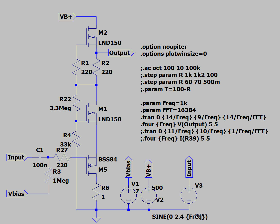
1.7 Vrms at its input give an output of 161 Vrms with a THD of 0.019953%:
By increasing the local feedback, THD can be reduced to ppm and subppm values at the expense of the gain.
1.7 Vrms at its input give an output of 161 Vrms with a THD of 0.019953%:
Code:
Harmonic	Frequency	 Fourier 	Normalized	 Phase  	Normalized
 Number 	  [Hz]   	Component	 Component	[degree]	Phase [deg]
    1   	1.000e+03	2.282e+02	1.000e+00	    0.09°	    0.00°
    2   	2.000e+03	4.545e-02	1.992e-04	   86.56°	   86.48°
    3   	3.000e+03	2.613e-03	1.145e-05	   15.97°	   15.88°
    4   	4.000e+03	7.292e-04	3.195e-06	  -78.80°	  -78.89°
    5   	5.000e+03	3.543e-04	1.552e-06	   53.92°	   53.84°
    6   	6.000e+03	1.518e-04	6.649e-07	 -175.28°	 -175.37°
    7   	7.000e+03	1.013e-04	4.440e-07	  121.06°	  120.98°
    8   	8.000e+03	1.477e-04	6.473e-07	  172.03°	  171.94°
    9   	9.000e+03	9.606e-05	4.209e-07	  168.42°	  168.33°
Total Harmonic Distortion: 0.019953%(0.019935%)
By increasing the local feedback, THD can be reduced to ppm and subppm values at the expense of the gain.
Attachments

Cute, but tith the substantial positive bias available through the FB pair, you can use regular old N-fets too... 🙂 For a little one, also good to 450V, try the DN3545N3...and even as I type it again I wish there were an N5...LOL
Douglas
Douglas
Last edited:
Thanks Bandersnatch!
This evening I will propose here a simple design for an hybrid EL84 SE where this last mosfet driver is DC coupled to the p-mosfet on the bottom of the EL84 with UNSET+UL: the whole system is biased by the voltage at the gate of driver's p-mosfet (that sets the output dc voltage at the driver, that set the bias of the output stage).
I'm thinking at the EL84 just because even with alot of a-g1 feedback it won't be that much heat to dissipate for the p-mosfet at the bottom of the tube.
At the same time it should mean goof DF and THD.
Sounds like a fine plan. The drive voltage of the EL84 is small( before FB ), and you will be effectively turning the depletion-mode FET into a very fine triode to drive it with. Looking forward to examining your work.
A question: since you're turning the FET into a triode, what is to stop you from using a constant current, active plate load? I am probably neglecting an important current loop, but with a triode, a horizontal load line nets amplification = mu, and since you set mu with the FB path...
Douglas
A question: since you're turning the FET into a triode, what is to stop you from using a constant current, active plate load? I am probably neglecting an important current loop, but with a triode, a horizontal load line nets amplification = mu, and since you set mu with the FB path...
Douglas
Last edited:
Thanks for your feedback Bandersnatch, isn't M2, the top LND150, already a CCS in the previous schematic?
This is the hybrid mosfet-EL84 amp (very far from being optimized):
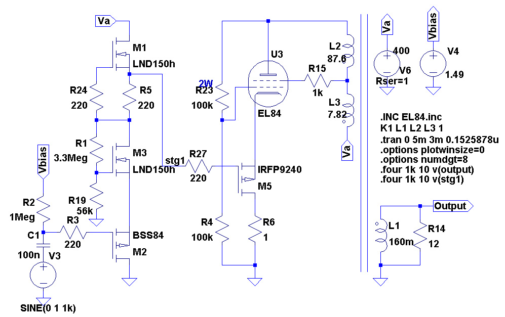
Has a DF of 19 and gives 1 Wrms with 750 mVrms at its input with the following simulated distortion figure:
7 Wrms with 2 Vrms at its input with the following simulated distortion figure:
This is the hybrid mosfet-EL84 amp (very far from being optimized):
Has a DF of 19 and gives 1 Wrms with 750 mVrms at its input with the following simulated distortion figure:
Code:
Harmonic	Frequency	 Fourier 	Normalized	 Phase  	Normalized
 Number 	  [Hz]   	Component	 Component	[degree]	Phase [deg]
    1   	1.000e+03	4.025e+00	1.000e+00	  176.04°	    0.00°
    2   	2.000e+03	8.557e-04	2.126e-04	 -121.70°	 -297.75°
    3   	3.000e+03	4.404e-04	1.094e-04	  179.95°	    3.90°
    4   	4.000e+03	1.800e-05	4.473e-06	  -18.89°	 -194.93°
    5   	5.000e+03	1.489e-05	3.699e-06	   -4.69°	 -180.73°
    6   	6.000e+03	3.773e-06	9.374e-07	    9.47°	 -166.57°
    7   	7.000e+03	2.938e-06	7.299e-07	    1.80°	 -174.24°
    8   	8.000e+03	2.817e-06	6.998e-07	   -0.67°	 -176.72°
    9   	9.000e+03	2.523e-06	6.269e-07	   -0.19°	 -176.23°
   10   	1.000e+04	2.264e-06	5.624e-07	   -0.03°	 -176.08°
Total Harmonic Distortion: 0.023919%(0.023919%)
7 Wrms with 2 Vrms at its input with the following simulated distortion figure:
Code:
Harmonic	Frequency	 Fourier 	Normalized	 Phase  	Normalized
 Number 	  [Hz]   	Component	 Component	[degree]	Phase [deg]
    1   	1.000e+03	1.058e+01	1.000e+00	  176.03°	    0.00°
    2   	2.000e+03	5.258e-03	4.968e-04	  140.00°	  -36.03°
    3   	3.000e+03	2.693e-02	2.545e-03	  175.48°	   -0.55°
    4   	4.000e+03	5.037e-03	4.760e-04	  -88.73°	 -264.76°
    5   	5.000e+03	7.796e-03	7.366e-04	  -12.65°	 -188.68°
    6   	6.000e+03	1.682e-03	1.590e-04	   78.35°	  -97.68°
    7   	7.000e+03	2.121e-03	2.004e-04	  159.14°	  -16.89°
    8   	8.000e+03	2.852e-04	2.695e-05	 -105.20°	 -281.23°
    9   	9.000e+03	5.175e-04	4.890e-05	  -28.30°	 -204.33°
   10   	1.000e+04	1.957e-05	1.849e-06	 -139.10°	 -315.13°
Total Harmonic Distortion: 0.274975%(0.274978%)
Attachments
Last edited:
SpreadSpectrum, you are absolutely correct! Thanks!
This morning, in another of the shower "light bulb went on" moments, I've seen another way to bias the system keeping everything DC coupled: ground the gate of the p-mosfet and biasing the system by substituing R19 with a trimmer (reference need to be negative and possibly variable).
And this make me think of another option: substitute also R4 with a trimmer, and have a system where you can set the curves of the driver and the output stage (to every R4 value there's a R19 value that sets the bias correctly, and at the same time the local feedback is adjusted accordingly) to personal tastes.
In a specific (and I would say limited) range, R19 could become a pot to change the harmonic content of the amp (and R4 automized to keep the bias stable).
I hope to have time to simulate it during the weekend, waiting next months to restart building ideas.
I've optimized the driver, with 700 mVrms at its input, output (not loaded) swings 150 Vrms with 0,02% THD:
Of course, if some 2nd harmonic is needed, it can be loaded by a resistor instead of a CCS.
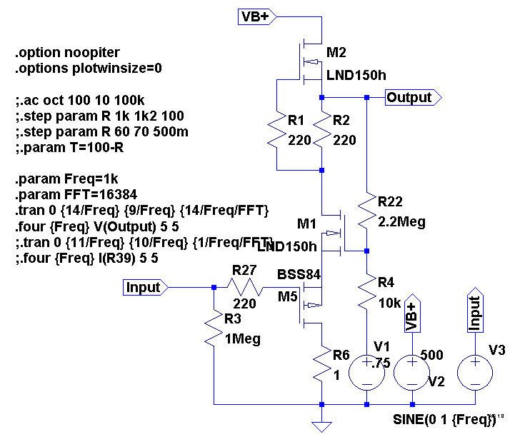
Code:
Harmonic	Frequency	 Fourier 	Normalized	 Phase  	Normalized
 Number 	  [Hz]   	Component	 Component	[degree]	Phase [deg]
    1   	1.000e+03	2.141e+02	1.000e+00	   -2.63°	    0.00°
    2   	2.000e+03	3.591e-02	1.678e-04	   39.97°	   42.60°
    3   	3.000e+03	3.030e-02	1.415e-04	   73.56°	   76.19°
    4   	4.000e+03	1.244e-02	5.810e-05	  158.56°	  161.19°
    5   	5.000e+03	1.003e-02	4.685e-05	 -116.52°	 -113.89°
    6   	6.000e+03	4.778e-03	2.232e-05	  -32.05°	  -29.42°
    7   	7.000e+03	3.475e-03	1.623e-05	   52.79°	   55.42°
    8   	8.000e+03	1.778e-03	8.307e-06	  137.20°	  139.83°
    9   	9.000e+03	1.221e-03	5.702e-06	 -137.84°	 -135.21°
Total Harmonic Distortion: 0.023368%(0.023356%)
Of course, if some 2nd harmonic is needed, it can be loaded by a resistor instead of a CCS.
Attachments
It's similar to my Corona amp input stage except has all of the feedback local to itself (and this one is all sand).
I love the series differential stage with active load. Two high-impedance inputs, and low Zout from the CCS source. What's not to love?
I love the series differential stage with active load. Two high-impedance inputs, and low Zout from the CCS source. What's not to love?
I have been tinkering with something similar. Just take out the top LND150 and install a tube.
I'm still playing with small scale (6W6) since I have lots and they are hard to kill. There are many "knobs" to turn here, so this may be the time to go from real parts back into the LT spice world.
I'm still playing with small scale (6W6) since I have lots and they are hard to kill. There are many "knobs" to turn here, so this may be the time to go from real parts back into the LT spice world.
I post here a variation of the concept of the local feedback on pentodes.
It is very basic, very far from being optimized and just proposed as a concept to be developed.
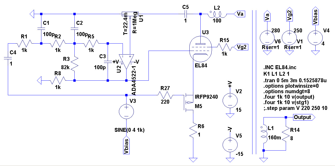
The pentode is biased and driven by the cathode as per George's circuit, but g1 is fed only by the distortion of the output tube instead of the full signal scaled down.
The result is that the gain is unchanged compared to the pentode mode (I get 360Vpp at its anode with 8Vpp on its input), DF is 18 and a very badly implemented circuits gives 0,3% THD at 3 Wrms.
It is very basic, very far from being optimized and just proposed as a concept to be developed.
The pentode is biased and driven by the cathode as per George's circuit, but g1 is fed only by the distortion of the output tube instead of the full signal scaled down.
The result is that the gain is unchanged compared to the pentode mode (I get 360Vpp at its anode with 8Vpp on its input), DF is 18 and a very badly implemented circuits gives 0,3% THD at 3 Wrms.
Code:
Harmonic	Frequency	 Fourier 	Normalized	 Phase  	Normalized
 Number 	  [Hz]   	Component	 Component	[degree]	Phase [deg]
    1   	1.000e+03	6.764e+00	1.000e+00	    0.01°	    0.00°
    2   	2.000e+03	2.256e-02	3.334e-03	  101.46°	  101.46°
    3   	3.000e+03	1.046e-02	1.547e-03	   16.89°	   16.88°
    4   	4.000e+03	3.965e-03	5.862e-04	  -69.13°	  -69.14°
    5   	5.000e+03	2.387e-03	3.529e-04	 -154.52°	 -154.53°
    6   	6.000e+03	1.185e-03	1.752e-04	  118.39°	  118.38°
    7   	7.000e+03	7.555e-04	1.117e-04	   31.74°	   31.74°
    8   	8.000e+03	4.351e-04	6.432e-05	  -56.38°	  -56.39°
    9   	9.000e+03	2.847e-04	4.209e-05	 -144.33°	 -144.33°
   10   	1.000e+04	1.778e-04	2.628e-05	  127.37°	  127.37°
Total Harmonic Distortion: 0.374539%(0.374546%)
Attachments
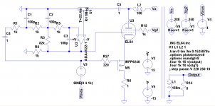
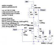
I've found this schematic on Pinterest for a variation of the "Shade" and I tried to simulate it.
It gives around 8 Wrms with a Zout of 0.035 Ohm (that's a DF of 228).
C2 was 1000 uF, I've used 10u to speed up the simulation.

Has anyone tried something similar?
It gives around 8 Wrms with a Zout of 0.035 Ohm (that's a DF of 228).
C2 was 1000 uF, I've used 10u to speed up the simulation.
Has anyone tried something similar?
Attachments
- Home
- Amplifiers
- Tubes / Valves
- Single Ended: the pentode retaliation