An interesting circuit, But it is not Schade FB since the NFB path is thru U2 to the Kathode of U1, not the Plate of U1.
The NFB path is attenuated by ~1/mu of U2.
Further, the OPT winding resistance are not included in the NFB, DF of 228 is unlikely.
Perhaps a DF of 2.28, that is possible. 🙂
The NFB path is attenuated by ~1/mu of U2.
Further, the OPT winding resistance are not included in the NFB, DF of 228 is unlikely.
Perhaps a DF of 2.28, that is possible. 🙂
The feedback path thru C1, U4 to U2's grid is positive Fdbk. increasing U1 gain. So no wonder the output Z is so low, with so much gain available in the U3 plate to U2 plate and on around U1, N Fdbk loop. Distortion might be higher than usual. Not sure what happens to the 1/mu effect of U2 on N Fdbk with the positive Fdbk on it's grid. Interesting circuit. Do you have any distortion figure?
From the U2 perspective, seems that the pos. Fdbk at the grid is making the cathode follow it, so that the neg. Fdbk on the plate (going the other way) appears to have a greater amplitude. Perverted analysis maybe. Curious what the simulation thinks. What is the final gain?
From the U2 perspective, seems that the pos. Fdbk at the grid is making the cathode follow it, so that the neg. Fdbk on the plate (going the other way) appears to have a greater amplitude. Perverted analysis maybe. Curious what the simulation thinks. What is the final gain?
Last edited:
Zintolo's simulation would be more accurate if the OPT wdg DC resistances where included.
I don;t see them anywhere.
I don;t see them anywhere.
@jhstewart9:
The OPT has 150H primary inductance, 3500 Ohm Ra, 40%UL, and the DC resistance of both primary and secondary are in the simulation: 45 Ohm for the primary and 0.2 Ohm for the secondary.
Playing with the feedback pot U4 it is possible to achieve even negative Zout, but in reality I think this would cause instability.
@smoking-amp:
isn't it another way to have only distortion as current feedback on the cathode of V1, comparing the signal at the infeed and output of U3 through U2?
I say so because it has a similar behaviour of gain vs Zout as the other circuits I tried with similar approach.
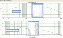
The gain in current configuration is 13.73 (or 22.76 dB as you prefer to express it).
This is the 1 Wrms simulation with 8 Ohm load and 290 mVp (205 mVrms) as input signal:
and this is with same input voltage and 12 Ohm load, to check Zout:
I think the circuit can be highly improved CCS loading the driver or applying local feedback on driver and/or output stage.
The OPT has 150H primary inductance, 3500 Ohm Ra, 40%UL, and the DC resistance of both primary and secondary are in the simulation: 45 Ohm for the primary and 0.2 Ohm for the secondary.
Playing with the feedback pot U4 it is possible to achieve even negative Zout, but in reality I think this would cause instability.
@smoking-amp:
isn't it another way to have only distortion as current feedback on the cathode of V1, comparing the signal at the infeed and output of U3 through U2?
I say so because it has a similar behaviour of gain vs Zout as the other circuits I tried with similar approach.
The gain in current configuration is 13.73 (or 22.76 dB as you prefer to express it).
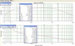
This is the 1 Wrms simulation with 8 Ohm load and 290 mVp (205 mVrms) as input signal:
Code:
Harmonic    Frequency     Fourier     Normalized     Phase      Normalized
 Number       [Hz]       Component     Component    [degree]    Phase [deg]
    1       1.000e+03    3.983e+00    1.000e+00       -1.38°        0.00°
    2       2.000e+03    3.647e-02    9.156e-03       71.75°       73.13°
    3       3.000e+03    1.044e-03    2.622e-04     -157.61°     -156.23°
    4       4.000e+03    9.120e-04    2.290e-04     -133.98°     -132.60°
    5       5.000e+03    2.754e-04    6.914e-05     -177.44°     -176.06°
    6       6.000e+03    2.254e-04    5.660e-05      178.78°      180.16°
    7       7.000e+03    1.987e-04    4.989e-05     -179.01°     -177.63°
    8       8.000e+03    1.739e-04    4.366e-05     -178.96°     -177.58°
    9       9.000e+03    1.544e-04    3.877e-05     -179.11°     -177.73°
Total Harmonic Distortion: 0.916372%(0.916441%)
and this is with same input voltage and 12 Ohm load, to check Zout:
Code:
Harmonic    Frequency     Fourier     Normalized     Phase      Normalized
 Number       [Hz]       Component     Component    [degree]    Phase [deg]
    1       1.000e+03    3.990e+00    1.000e+00       -1.30°        0.00°
    2       2.000e+03    2.515e-02    6.302e-03       74.84°       76.14°
    3       3.000e+03    2.406e-03    6.029e-04      172.54°      173.84°
    4       4.000e+03    5.990e-04    1.501e-04     -143.18°     -141.88°
    5       5.000e+03    2.442e-04    6.120e-05     -175.32°     -174.02°
    6       6.000e+03    2.252e-04    5.643e-05      179.51°      180.81°
    7       7.000e+03    1.964e-04    4.923e-05     -179.49°     -178.19°
    8       8.000e+03    1.715e-04    4.298e-05     -179.40°     -178.09°
    9       9.000e+03    1.523e-04    3.818e-05     -179.49°     -178.18°
Total Harmonic Distortion: 0.633332%(0.633429%)
I think the circuit can be highly improved CCS loading the driver or applying local feedback on driver and/or output stage.
Last edited:

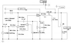
Thanks to google I've found the site where the schematic has been posted.
Credits go to: https://www-ne-jp.translate.goog/as..._sl=ja&_x_tr_tl=en&_x_tr_hl=it&_x_tr_pto=wapp
(this link shows the page automatically translated from japanese to english)
Credits go to: https://www-ne-jp.translate.goog/as..._sl=ja&_x_tr_tl=en&_x_tr_hl=it&_x_tr_pto=wapp
(this link shows the page automatically translated from japanese to english)
Back when Steve Bench published his inverted triode experiments, I began a lot of experiments using them in both the forward and feedback path of audio amps. Many of my experiments involved guitar amps and unique effects, but I did try something very similar to this. I had several hundred 12AT7 type tubes to play with so they were my go to tube for science experiments as I had a lot and it is easy to try other tubes with a similar pinout. I don't remember the details of the exact schematic, but the plate of the small triode was tied to the plate of the output tube.I've found this schematic on Pinterest for a variation of the "Shade" and I tried to simulate it.
Has anyone tried something similar?
I can relate some real world facts that this simulation will not reveal. Connecting the plate of a 12AT7 or other similar tube directly to the plate of an output tube in a guitar amp, plugging in a guitar, setting the controls for the heart of the sun, and cutting loose on the guitar will result in a short unhappy life for the 12AT7 and possibly several other parts. In normal HiFi use the plate voltage on an output tube will approach 2X the B+ voltage. It will be much higher in a guitar amp driven to clipping into a speaker operating near it's resonance.
A 12AT7, 12AX7, or 5751 will flash over internally, and once the fireworks cease, the tube may or may not still function, but it will likely have a H-K short or degraded isolation. I also blew up a couple 12AU7's and one 12BH7 before abandoning this experiment. Both of those tubes are rated for TV vertical sweep duty allowing a peak positive plate voltage of 1200 or 1500 volts. A 6S4A will survive in a SE guitar amp that used an EL34 or 6L6GC, but I didn't beat on it too hard. I had planned to take this concept further using a more modern vertical output tube like the 6EM7, but it never got built.
Thanks @Tubelab_com, I think that happensa because when in clipping the amp has very high Rout, and at speaker's resonance the impedance is very high, so the loadline of the tube is almost horizontal, so its plate swings from 30-50V up to very high values before reaching Ia=0.In normal HiFi use the plate voltage on an output tube will approach 2X the B+ voltage. It will be much higher in a guitar amp driven to clipping into a speaker operating near it's resonance.
Good to know it that is better to use this kind of circuits with horn loaded fullrange speakers due to their almost constant impedance vs frequency, and so stick on Hi-Fi use.
Thanks for the tip about a possible substitute for the 12AT7!I had planned to take this concept further using a more modern vertical output tube like the 6EM7, but it never got built.
Thanks for the explanation @jhstewart9 , am I correct saying that the positive current feedback injected into U1's cathode contains only the distortion of the output tube?OPT Winding Resistance cancelled by negative resistance at the output tube drive point. 🙂 👍
During lunch break I've done some simulations, and it seems that the resistor loaded driver stage gives best performance.I think the circuit can be highly improved CCS loading the driver or applying local feedback on driver and/or output stage.
By CCS loading the drive there's a small THD advantage, but all harmonics become similar, whilst with 68k the THD is slightly higher, but 2H is more than 40dB below, then there are almost another 40 dB between 2H and 3H, and all others falls nicely.
When an SE amp is driven into clipping it will transition through a period of time where the output tube is cutoff. If there is no load on the OPT the plate voltage can theoretically reach infinity. In reality the voltage will rise until a path of conduction is found. This is usually an arc somewhere. It can be an arc inside the output tube, inside the OPT, or more often between pin 3 (plate) and pin 2 (heater) of the output tube socket, or inside the base of the tube itself.Thanks @Tubelab_com, I think that happensa because when in clipping the amp has very high Rout, and at speaker's resonance the impedance is very high, so the loadline of the tube is almost horizontal, so its plate swings from 30-50V up to very high values before reaching Ia=0.
Good to know it that is better to use this kind of circuits with horn loaded fullrange speakers due to their almost constant impedance vs frequency, and so stick on Hi-Fi use.
Thanks for the tip about a possible substitute for the 12AT7!
A guitar amp is worse case because they are often driven well into clipping, and the resonance of a typical guitar speaker is usually inside the guitar's frequency range. The impedance of the speaker at this point depends on the timing of the guitar player and many other factors, but transitions well above 30 to 40 ohms are common. I have measured peak voltages of well over 2500 volts in a push pull guitar amp that ran a pair of 6L6GC's on 430 volts. I did not measure a SE guitar amp, but similar voltages can be expected. The losses in the OPT greatly affect this peak voltage as does the speaker's behavior.
Later experiments with cathode feedback seen here, and in the Tubelab SSE amp reveal that it reduces the peak voltage seen in intentional misloading of a cheap OPT and may be helpful in preventing blown 12AT7's, but the SSE and my CFB experiments happened after my inverted triode experiments, so I never investigated further.
In order to find the weak links in my HiFi amp designs, all of them are subjected to my lousy guitar playing at levels far beyond what's seen in a typical HiFi setup.
The vertical output tubes that I mentioned have a rather low Mu, so they may not be the best choice here. One needs to look for a suitable triode that can live with a lot of voltage on it's plate. The 12AT7 has a Mu of 70, but it was originally intended for FM radio tuner applications which usually run at a rather low voltage.
isn't it another way to have only distortion as current feedback on the cathode of V1, comparing the signal at the infeed and output of U3 through U2?
I say so because it has a similar behaviour of gain vs Zout as the other circuits I tried with similar approach.
Yes, it looks just like Hawksford's Error Correction thing. Feeding the error ALL the way back to where it sums with the input to form a positive Fdbk loop.
This scheme is then capable of over-correcting the error by going past the null error point on the pot. What I don't see is where it is sampling output current to create a negative resistance, to get the extreme damping factor. Maybe over doing the Error Correction past null setting on the pot gives the same effect by feeding back extra signal drive to then effectively compensate for OT resistive loss. So it is assuming load current is proportional to load V. My guess would be that when the pot adjustment reaches extreme damping factor, the tube error may becoming overcompensated, causing a rise in (inverted) distortion again.
Last edited:
I think that U2 is looking at a voltage on its plate, a voltage on its grid, and gives a voltage on its cathode, then it's the resistor(s) on U2's cathode that transforms the voltage into current.What I don't see is where it is sampling output current to create a negative resistance, to get the extreme damping factor.
It is like that indeed: minimum THD isn't where DF is highest. The sequence is:My guess would be that when the pot adjustment reaches extreme damping factor, the tube error is overcompensated, causing a rise in (inverted) distortion again.
Minimum THD > highest DF > negative DF.
Optimization of #82:
To get the minimum THD and max Damping factor to coincide better.
Lift bottom of R5 and C2 above ground connection by 10 Ohms. Then take a 100K pot, U5, from top of 10 Ohm resistor to U1 cathode. Adjust U4 for minimum THD.
Adjust U5 for almost max damping. (just want to cancel OT primary resistance in order to remove OT magnetizing distortion)
Here is the subject amp filled out. The freq response looks like a problem, something I didn't expect.
Running two tests, one with an 8R load, the other with a loudspeaker simulator.
I've used a sub-circuit for the loudspeaker to keep the schematic from getting cluttered.
Running two tests, one with an 8R load, the other with a loudspeaker simulator.
I've used a sub-circuit for the loudspeaker to keep the schematic from getting cluttered.
Attachments
That is a problem. Maybe the internal Plate to grid capacitance of V2 is loading down the grid? (ie, preventing the positive Fdbk from working on the grid at HF)
Last edited:
I used the data sheet C's for the tube models. The parasitic C's for the EL34 will have to grafted on manually.That is a problem. Maybe the internal Plate to grid capacitance of V2 is loading down the grid? (ie, preventing the positive Fdbk from working on the grid at HF)
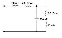
That will further restrict the HF. I put the OPT leakage reactance to 0.5 mH but no luck. The inductance is 150H.
Tomorrow I'll sim the OPT model alone, driven from a brute force source, check it's bare bones response.
And cut down more dead Ash trees. 🌳 Been watching the Ben Franklin documentary tonite, as always very well done by Ken Burns.👍
Last edited:
- Home
- Amplifiers
- Tubes / Valves
- Single Ended: the pentode retaliation