daanve,
physical relationships can be difficult subject matter. It’s easy to feel discombobulated.
physical relationships can be difficult subject matter. It’s easy to feel discombobulated.
Well TJ full music has type 50s for ~300 bucks a pair
50 (TJ Fullmusic. Mesh Plate. Matched Pair.) – DIY Hifi Supply
Someone also has a collection of NOS national unions on ebay for 500 bucks a pair. You don't have to pay 1000 bucks to EML to get a type 50 : )
While I am on the topic of TJ full music, take a look at the PX4 and the PX25. Both of those would definitely make an interesting amp as well.
I know exactly the National Union tubes you are talking about, there is a nice pair of NOS ST Tung-Sols too. The EML comment is more about knowing there is a safety net if NOS supplies run dry, but good to know there are others out there like TJ Fullmusic. The PX25 has also intrigued me, KR Audio makes a new production PX25 too. That's another cost-no-object type, but would be very exciting to build with. From my searching, best prices for NOS PX25 are in Japan. I have seen some pairs go for $700-800 USD at auction, a true bargain! 🙄 more common is around $1,000 USD.
LL9202 – Bartola(R) Valves
I was just looking at this - Ale really liked the 814 tube at one point. That's another idea. Not a common tube, but there must be some about including a few on eBay for reasonable money.
Interesting tube Andy, impressive linearity and curves stretch pretty far into A2 as well from Ale's curves on this page.
814 triode mode – Bartola(R) Valves
Ra of 2K makes it a good fit for a 6.5K load, however my LL9202 are the 50mA gapped model as opposed to the 85mA gapped model.
You all have given me a lot to think about, I appreciate the help 😀
Last edited:
Distortion is low at 350v a-k and 50mA into 5K.
Distortion is very low at 350v a-k and 50mA into 3K Lundahl.
daanve,
physical relationships can be difficult subject matter. It’s easy to feel discombobulated.
Then my advice is to learn some fundamentals about tube electronics 🙄
Hey SS - the 25T did come to mind as it is on my short list to build with, another A2 design with NFB. 3.25K 100mA OPT would suit well I think if the transformer is rewired. I have a batch of 25T (3C24) with Eimac grid / plate caps on hand. It biases with a positive grid voltage, had thought I might be able to forgo a negative supply if I choke load a direct-coupled cathode follower for the negative grid swings. Need to generate enough gain on the input for the feedback loop, but with the high mu of the 25T, very little closed loop gain will be needed for a good input sensitivity. Will keep this one in mind, might even try breadboarding it, I have a suitable mains transformer as well.
Would love to build with the type 50, but the price is intimidating! I was very seriously considering it at one point, even reached out to EML who say they are continuing production of their type 50. But seeing as a type 50 SET is a cost-no-object design already, I think I would want to get dedicated transformers. Will keep it in mind though 😉
The grid choke might introduce phase shifts that could complicate the application of feedback. I found little AC-DC 48V supplies from Meanwell that are stackable, so I have a +96V and -48V rails for the mosfet grid driver, and they are cheap.
I've got a globe Cunningham 50 that I came across at a local antique shop but I probably won't ever use it as I can't see paying enough to get more, to use it in a project. The idea of selling it scares me, though, because it looks too fragile to ship.
And to touch on the thread derail, the idea that decreased primary inductance would decrease distortion and increase bass response is so nonsensical that it really doesn't deserve anything but a passing mention so that new people aren't taken in by it. It is really a shame that such things are posted in this community.
May I ask a newbie question?
When you design SE amps, you set the loadline and working point to hit Vg1=Vk before, together or after Ik=0?
Thanks
When you design SE amps, you set the loadline and working point to hit Vg1=Vk before, together or after Ik=0?
Thanks
Of course, cathode current never gets to zero, and all real valves have a varying response between high current and low current regions. This varying responce is the source of all (classical) distortions.
When choosing loadlines, spend some time with a transparent rule and your chosen valve's plate voltage v. plate current per grid voltage curves. You'll quickly see that the most linear part of those curves (meaning: for a given change in grid voltage, how linear is the change in plate voltage?) happens up in the higher current and lower voltage region.
Then, you'll calculate how much power output your chosen linear loadline makes, and worry that the number isn't macho enough. For triode amplifiers there's a monotonic relationship (in the practicable region where we are) between lighter loading and lower distortion and lower output. Also true for push-pull; both, triodes only.
Maybe a really serious amplifier design should start with an actual design goal. I need to drive these two speakers to an average (0VU) of x SPL at listening position, and a peak of y SPL accommodated without too terrible effect. Translation from this to a loadline is a next step, not a beginning.
YOS,
Chris
When choosing loadlines, spend some time with a transparent rule and your chosen valve's plate voltage v. plate current per grid voltage curves. You'll quickly see that the most linear part of those curves (meaning: for a given change in grid voltage, how linear is the change in plate voltage?) happens up in the higher current and lower voltage region. Then, you'll calculate how much power output your chosen linear loadline makes, and worry that the number isn't macho enough. For triode amplifiers there's a monotonic relationship (in the practicable region where we are) between lighter loading and lower distortion and lower output. Chris
Thank you for this, Chris. Are you saying that in the case of 300b you'd prefer, say, 260v a-k and 70mA to 400v a-k and 50mA for a dissipation of 20W?
By "lighter loading" you mean the OPT primary is higher rather than lower, so less power out? By all means expand on this.
The grid choke might introduce phase shifts that could complicate the application of feedback. I found little AC-DC 48V supplies from Meanwell that are stackable, so I have a +96V and -48V rails for the mosfet grid driver, and they are cheap.
I've got a globe Cunningham 50 that I came across at a local antique shop but I probably won't ever use it as I can't see paying enough to get more, to use it in a project. The idea of selling it scares me, though, because it looks too fragile to ship.
Ah yes, adding a reactive component will complicate the feedback, a negative supply with a resistively/CCS loaded cathode or source follower is the safer route. I've attempted to trace the curves of the 3C24 on my tracer, a pulse tester like the utracer, but they do not play nicely together, need to investigate that further.
For the same reason you are afraid to sell, I am afraid to buy the type 50! Those old filaments are so delicate, $250 could vanish in the blink of an eye. I lost a ceramic base Taylor 801A this way, but thankfully the seller took responsibility. That 801A amp is my pie-in-the-sky project for now, I am gathering components for a final prototype, I'm hopeful I will be able to build it in a month or two, but I digress...
The choice of a region of the curves where linearity is higher (*always* for vacuum triodes meaning higher current and , necessarily, for any particular idling power dissipation, lower voltage) implies a lower peak output capacity. Practically speaking, you can't draw grid current. So, best case, you can only swing the grid voltage up to about zero, and down the same amount. This can be quite different than an idling position that lets you swing much further, but into much less linear regions.
The next thing you'll see, playing with a transparent rule on the plate curves, is that a more horizontal loadline is more linear than a less horizontal. The (inverse) slope of your ruler is the load impedance seen by the output stage. And you'll see that, again, peak output decreases as linearity increases. Everything is a choice between linearity and thermal conversion efficiency, as is so much in life.
To answer your specific question, I'd ask the question a different way: does the difference of about 2dB in peak output power rank higher in your design goals than somewhat less distortion and somewhat better speaker damping? That's your huckleberry.
YOS,
Chris
Last edited:
Oh yeah also, both of these valve linearity goals conspire *against* output transformer design issues. OPTs would love to be in a low impedance, low idling current, low turns ratio world. HiFi's just not a fair fight.
ch
ch
Last edited:
Serious question, is there any sort of price limit on the tubes?
In my mind if you sold the transformers as being used, they would probably go for about 200 a piece. So I would tend to think tubes in the 200 dollar per piece price range would be acceptable. But based on your previous statement, I am starting to think you might have a different standard. If so, that is totally fine, but I would like to know so that I can narrow my search.
In my mind if you sold the transformers as being used, they would probably go for about 200 a piece. So I would tend to think tubes in the 200 dollar per piece price range would be acceptable. But based on your previous statement, I am starting to think you might have a different standard. If so, that is totally fine, but I would like to know so that I can narrow my search.
Well I would say the PX25 is not practical due to price and rarity, but you have rekindled my interest in the type 50. The price for a NOS pair is not horrendous compared to high-end new production DHTs. Could build the amp with a TJ Fullmusic pair, then go NOS once finalized.
A 6.5K:8ohm 50mA 100H transformer really isn't a bad match for the 50 with its 1.8K Rp. Say a 450V 50mA bias point, LL9202 wired for 6.5K has 0.8dB in losses, would still give close to a 4W amplifier. Could also do 425V 50mA for tube longevity.
The driver would need to swing 170Vpk-pk. From my tubes on hand, trioded D3a seems a good choice. There is one other high gm pentode in my collection that would work well too, or other 300B driver types.
Filament for the 50 is 7.5V 1.25A, same as the 801A. If using Rod Coleman regulators, I have spare filament transformers on hand already. The big question would be 1:1 interstage vs. grid choke. It's an intriguing idea, extra since I have many of the parts. But let's be honest, I am making excuses to do it 😛
Last edited:
Has anybody tried to use that transformer with a Pentode or a Beam Power tube, wired with the screen at the middle of the 4 series primary windings?
Example:
B+ at one end of 4 windings; 2 windings in series from there to the screen; and 2 more windings in series from there to the plate.
A 7591 with the screen at 50% (negative feedback) the plate impedance, rp, should be low enough to work into the 23k load, without any other negative feedback.
(50% of the way from Beam Power mode to 100% Triode wired mode).
Or, do the first 2 series windings not couple well enough to the other 2 series windings?
Is there too much leakage inductance?
Last edited:
May have been mentioned already, but what about a 6S45P spud amp? 6K5/50mA should be the sweet spot for 6S45p.
Or, do the first 2 series windings not couple well enough to the other 2 series windings?
Is there too much leakage inductance?
One would want to make sure that some secondary sections are paralleled between the two winding bobbins.
--------
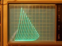
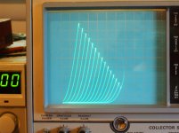
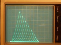
I see some $$$$ tubes being bandied about here. I assume you all are familiar with the latest "new" Series Schade (= UnSET, CED at Tubelab) technique. One can take a $10 TV Sweep tube and make it into a 211 type curve set (except using lower B+ and higher current for practical B+ supply and OT impedance).
1) 6HJ5 native internal triode curves (50mA/div Vert., 50V/div Horiz., Mu 4.2)
2) 6HJ5 UnSET triode curves ("" , "" , Mu 4 )
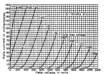
3) 211 triode curves
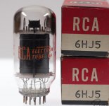
4) 6HJ5 pic
Nothing special about the 6HJ5 (24 Watt TV diss = 35 Watt audio tube, $12), most any TV Sweep or standard Audio type will do. The amount of 2nd harmonic in the curve set can be adjusted by the local Fdbk gain setting. (ie, 300B 2nd H easy to emulate)
Attachments
Last edited:
smoking-amp,
Good point!
Quote:"One would want to make sure that some secondary sections are paralleled between the two winding bobbins".
I think that may be why some people have trouble using Lundahl output transformers, they do not observe that principle.
So in regards to my Post # 55, I would also recommend that instead of putting all 4 primaries in series,
connect 1 winding from one bobbin in parallel with 1 winding from the other bobbin, and then put the other 2 windings in parallel (also are from opposite bobbins). Then connect those 2 sets in series, and tie the 50% point to the screen.
That would assure that the coupling from the plate to the screen have low enough leakage inductance, be good enough to use it that way.
Now the primary would be capable of more quiescent DC current, but would be 1/4 of the primary impedance, and and 1/4 of the DCR.
Last edited:
May have been mentioned already, but what about a 6S45P spud amp? 6K5/50mA should be the sweet spot for 6S45p.
No one has mentioned it, thanks for the idea, I will look into it! Reminds me that I have been quietly collecting E55L for a spud design, could potentially marry these two projects into one.
I see some $$$$ tubes being bandied about here. I assume you all are familiar with the latest "new" Series Schade (= UnSET, CED at Tubelab) technique. One can take a $10 TV Sweep tube and make it into a 211 type curve set (except using lower B+ and higher current for practical B+ supply and OT impedance).
1) 6HJ5 native internal triode curves (50mA/div Vert., 50V/div Horiz., Mu 4.2)
2) 6HJ5 UnSET triode curves ("" , "" , Mu 4 )
3) 211 triode curves
4) 6HJ5 pic
Nothing special about the 6HJ5 (24 Watt TV diss = 35 Watt audio tube, $12), most any TV Sweep or standard Audio type will do. The amount of 2nd harmonic in the curve set can be adjusted by the local Fdbk gain setting. (ie, 300B 2nd H easy to emulate)
Hi smoking-amp - I was not familiar with the UNSET / CED / crazy fdbk circuit, might be over my head but reading into it now, very impressive triode-like curves you've posted here and elsewhere. Have you listened to any of these breadboarded sweep tube output stages?
I haven't made an amplifier yet with the UnSET technique, just trying it out on the curve tracer so far. Once I get past taxes/paperwork I will be building one. Already have the parts at hand for both a SE version and a P-P version.
George (Tubelab) has been building and testing these type of amplifiers, developing a PC board too. Although I think he has been using a higher gain figure than I've been curve tracing with, which will put some 2nd H into the sound. (I'll let him work out any kinks, like mysteriously blown MosFets, before I build one. It works well on the curve tracer.)
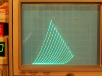
The technique also allows for more power output than would normally be expected from a given tube, since the driver power is added to it.
a) 6P41S in UnSET (cheap and available Russian tube)
b) 6P41S native internal triode mode
George (Tubelab) has been building and testing these type of amplifiers, developing a PC board too. Although I think he has been using a higher gain figure than I've been curve tracing with, which will put some 2nd H into the sound. (I'll let him work out any kinks, like mysteriously blown MosFets, before I build one. It works well on the curve tracer.)
The technique also allows for more power output than would normally be expected from a given tube, since the driver power is added to it.
a) 6P41S in UnSET (cheap and available Russian tube)
b) 6P41S native internal triode mode
Attachments
Last edited:
- Home
- Amplifiers
- Tubes / Valves
- Single Ended Output Tube for Lundahl LL9202 50mA