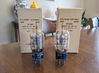
Got my hands on some functional 3C24. They run much cooler now that they're not filled with gas 😛
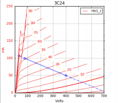
Here are the curves with a 6.5K 400V 50mA load line. This would make for 7-8W. Plate resistance at the idle point measured at 9.4K.
It isn't something I've done before so I will need to do some homework, but might try and generate a LTSpice model like I see Ale doing on his blog. Always trying to learn something new and having a simulation to tinker with would be helpful.

Here are the curves with a 6.5K 400V 50mA load line. This would make for 7-8W. Plate resistance at the idle point measured at 9.4K.

It isn't something I've done before so I will need to do some homework, but might try and generate a LTSpice model like I see Ale doing on his blog. Always trying to learn something new and having a simulation to tinker with would be helpful.
With that rp and stage gain, I don't think even 100% local feedback would get you to your Zout target, so it looks like a two stage feedback approach will be necessary.
What is your sensitivity requirement at the input? From there you can figure how much excess gain you need in the other stage for feedback.
Any tube ideas for the other stage?
Edit: Eyeballing the curves, you should have a very 2nd-dominant spectrum from this up until clipping.
What is your sensitivity requirement at the input? From there you can figure how much excess gain you need in the other stage for feedback.
Any tube ideas for the other stage?
Edit: Eyeballing the curves, you should have a very 2nd-dominant spectrum from this up until clipping.
I would shoot for a 2Vrms input sensitivity, good for my DAC and better than what is needed for my phono stage.
I was looking over another DIYers schematic in a similar design that used EF86, I had thought to try E80F, a near-equivalent. So my real early thought was to try E80F > 6AH4 CF > 3C24.
Here is some very armchair feedback math.
Voltage gain on that 6.5K 3C24 load line looks to be about 9. E80F gain from the datasheet with a 220K resistive load and 400V B+ is 200, just going to say 180 for some real world error. Cathode follower gain will be less than unity, so let's say 0.95.
That would make the open loop voltage gain of the amplifier ~1540.
To drive the 3C24 to full output with a 2Vrms input, the closed loop voltage gain of the E80F will need to be: 120Vpp / 5.6Vpp = 22
That would make the theoretical closed loop voltage gain of the amplifier 188, meaning 18.2dB of feedback could be applied in that arrangement with a feedback fraction of 0.00466.
Output impedance would be reduced by a factor of (1+AB) = (1+(1540*0.00466)) = 8.17
So estimating with a 9.4K plate resistance, output impedance on the OPT primary would be (9400/8.17)+600ohm DCR of the primary = 1750.
That's a damping ratio of 3.7 with a 6.5K primary, so seems viable assuming my math is accurate. I've only recently picked this up, so that is not necessarily a forgone conclusion 🙄
Last edited:
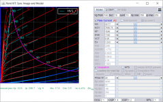
I have a functioning LTSpice model for the 3C24 now using the Dmitry Composite tool. Working in simulation, but might need to be further optimized. I prioritized matching the model within the operational area of a potential amplifier.
Here are the plate curves of the model overload on top of the curves I traced.
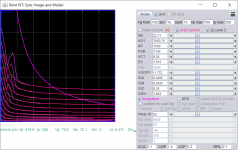
And grid current over the current measured on my tracer.
Putting together a simulation circuit using E80F and 6AH4, plate to cathode feedback using your PMOS buffered feedback circuit, SpreadSpectrum. We'll see how it works out 🙂
Here are the plate curves of the model overload on top of the curves I traced.

And grid current over the current measured on my tracer.

Putting together a simulation circuit using E80F and 6AH4, plate to cathode feedback using your PMOS buffered feedback circuit, SpreadSpectrum. We'll see how it works out 🙂
Thanks for the ideas everyone. Paralleling the primary windings is interesting, a lower primary Z at a higher current rating would open up many more possibilities. I may touch base with Lundahl / Kevin at K&K Audio and get their input.
Paralleling the primary windings is normally not recommended by Lundahl. It's likely related to their winding scheme. I would contact them directly.
I know for certain that this transformer worked really bad on the low impedance with rather poor high frequency response: 814 SE Amplifier: Custom Output Transformers – Bartola(R) Valves
Lower impedance is also not great at 0.8 dB power loss.
At 11K and 50 mA it's a good match to a 211. 100H will be good enough. I am sure there are other tubes as well.
However if the output power is less than rated, one can use more current. 50 mA is not a barrier beyond which one cannot go. The transformer is rated 25W @30Hz.
With the 211 the typical power will be 10W with 50 mA. So one can either leave as is and get 10W below 20Hz (sic!)....or can use mode current.
If one uses 60 mA then the DC induction will go from 0.9T to 1.08T. So the room left for the signal will go down to 0.52T (originally 0.7T) for the same total induction of 1.6T. This means that signal one can apply at 30Hz will be 390V RMS which means about 14W @30Hz. At 1200V plate voltage with 11K the 211 should give this kind of power.
Last edited:
Hey 45 - thanks, I did reach out to Kevin at K&K Audio, in the past they have directed me to him with technical questions, haven't heard back, I'll shoot Lundahl an email.
I think Ale was using the 85mA gapped LL9202, regardless the HF response is not great on the 50mA model. Wired for 6.5K in an 801 A2 prototype using plate to driver cathode NFB, HF rolloff was abrupt at around 15-16kHz, down 2-3dB at 20kHz if memory serves. It was worse wired for 11K. They also seem to have a ~20khZ resonance seen on square wave below.

These transformers didn't cut it in that 801A design, so custom transformers from Sowter will replace them, the reason why I have them on hand. They have issues, no doubt, but subjectively they still sound quite good, so thought it was worth asking opinions on what to do with them.
The B+ for a 211 design is too hot for my household, as much as I would love to dabble in the 1kV+ transmitters. Given the HF response is best at 6.5K, that's the direction I am likely to go. Pushing the current a little bit would be desirable. If I could go 60-75mA with in a 6-8W amplifier, that would be great.
I think Ale was using the 85mA gapped LL9202, regardless the HF response is not great on the 50mA model. Wired for 6.5K in an 801 A2 prototype using plate to driver cathode NFB, HF rolloff was abrupt at around 15-16kHz, down 2-3dB at 20kHz if memory serves. It was worse wired for 11K. They also seem to have a ~20khZ resonance seen on square wave below.

These transformers didn't cut it in that 801A design, so custom transformers from Sowter will replace them, the reason why I have them on hand. They have issues, no doubt, but subjectively they still sound quite good, so thought it was worth asking opinions on what to do with them.
The B+ for a 211 design is too hot for my household, as much as I would love to dabble in the 1kV+ transmitters. Given the HF response is best at 6.5K, that's the direction I am likely to go. Pushing the current a little bit would be desirable. If I could go 60-75mA with in a 6-8W amplifier, that would be great.
If you use it as 6.5K, for 75mA you will be causing a DC induction of 1.35T leaving just 0.25T for the signal. This might sound too little but in reality those original 575V RMS at 30Hz become 205V RMS. That's 6.5W @30Hz as you would like.
It looks like your 50mA operating point already gets you to 80% max dissipation of the 3C24. You could just push current and voltage up a bit and get a bit more power out. I have been trying to design to keep these tubes at 90% so that the plate stays hot enough for good gas absorption.
A 211 could also be operated at a much lower plate voltage in A2. It may not be a great match for your output transformer since a 75W plate is a bit overkill, but I'll probably end up getting some Chinese 211 to play with at some point. The curves look ridiculously linear and I want to see how that works out in this 2-stage A2 feedback scheme.
A 211 could also be operated at a much lower plate voltage in A2. It may not be a great match for your output transformer since a 75W plate is a bit overkill, but I'll probably end up getting some Chinese 211 to play with at some point. The curves look ridiculously linear and I want to see how that works out in this 2-stage A2 feedback scheme.
Hey 45 - thanks, I did reach out to Kevin at K&K Audio, in the past they have directed me to him with technical questions, haven't heard back, I'll shoot Lundahl an email.
I think Ale was using the 85mA gapped LL9202, regardless the HF response is not great on the 50mA model. Wired for 6.5K in an 801 A2 prototype using plate to driver cathode NFB, HF rolloff was abrupt at around 15-16kHz, down 2-3dB at 20kHz if memory serves. It was worse wired for 11K. They also seem to have a ~20khZ resonance seen on square wave below.
View attachment 935472
These transformers didn't cut it in that 801A design, so custom transformers from Sowter will replace them, the reason why I have them on hand. They have issues, no doubt, but subjectively they still sound quite good, so thought it was worth asking opinions on what to do with them.
The B+ for a 211 design is too hot for my household, as much as I would love to dabble in the 1kV+ transmitters. Given the HF response is best at 6.5K, that's the direction I am likely to go. Pushing the current a little bit would be desirable. If I could go 60-75mA with in a 6-8W amplifier, that would be great.
Well in that case, I would probably go with the 300b (or PX4 if you want to be fancy). The naturally low plate impedance will counterbalance the capacitance of the transformer.
If you wrap a little bit of NFB around the 300b, you will get a pretty decent damping factor and HF extension.
If you use it as 6.5K, for 75mA you will be causing a DC induction of 1.35T leaving just 0.25T for the signal. This might sound too little but in reality those original 575V RMS at 30Hz become 205V RMS. That's 6.5W @30Hz as you would like.
It looks like your 50mA operating point already gets you to 80% max dissipation of the 3C24. You could just push current and voltage up a bit and get a bit more power out. I have been trying to design to keep these tubes at 90% so that the plate stays hot enough for good gas absorption.
Thanks for your technical know-how, 45. I might push it to 400V 60mA or 365V 65mA SpreadSpectrum. Think the plate gets cherry red around 15W in the 3C24. I'll experiment when the time comes. I will be using an adjustable Maida regulator, so can fine-tune the B+ easily and try different bias points.
A 211 could also be operated at a much lower plate voltage in A2. It may not be a great match for your output transformer since a 75W plate is a bit overkill, but I'll probably end up getting some Chinese 211 to play with at some point. The curves look ridiculously linear and I want to see how that works out in this 2-stage A2 feedback scheme.
That will be interesting to see. Looking forward to your 100TH design as well. I am probably a month away from a final 801A A2 prototype. I have assembled many of the parts for the final build, just need to check that box and it will be a go for chassis layout and design.
Well in that case, I would probably go with the 300b (or PX4 if you want to be fancy). The naturally low plate impedance will counterbalance the capacitance of the transformer.
If you wrap a little bit of NFB around the 300b, you will get a pretty decent damping factor and HF extension.
The lower plate impedance would help, as would NFB, no doubt, won't rule anything out. I am putting together a flexible single-ended prototyping board, so throwing together a design and taking some quick and dirty measurements should be relatively straightforward in a month or so.
Good, I really like the idea of a test fixture.
Why don't you test to see how much capacitance we are dealing with in the first place? That way you will actually know what the plate impedance should be.
Why don't you test to see how much capacitance we are dealing with in the first place? That way you will actually know what the plate impedance should be.
I might push it to 400V 60mA or 365V 65mA SpreadSpectrum. Think the plate gets cherry red around 15W in the 3C24. I'll experiment when the time comes. I will be using an adjustable Maida regulator, so can fine-tune the B+ easily and try different bias points.
Your load line on the datasheet curves looks perfectly symmetrical at 50mA/400V. On the curves from the tracer it looks like at 400V, it needs just a little more standing current to make symmetrical clipping. It looks like 60mA might be too much and push the asymmetry the other way. I think 400V/50mA is already quite close to optimal. Optimal might be just 55mA or so.
After all of the brainstorming and ideas offered on this thread, which I am grateful for, I did not decide on a use for my LL9202. Instead, I was inspired to work on another A2 transmitting triode design based on the HK54, so work has begun on that project.
I now have a few time-consuming amplifiers in the pipeline and without a well-defined use for the LL9202, I was considering selling them to finance other parts. But I recently came across something that I think could be a fun, low-parts-count design to breadboard and potentially build if the results are good...
The 6B5 / 6N6G is an interesting dual dissimilar triode in which one half is wired as a cathode follower and internally direct-coupled to the second triode which is run as a 0V grid bias A2 power triode. You simply apply 300V, all biasing is done internally. Neat! The cathode follower provides A2 grid current to the output. Recommended load of 7K with 300V 42mA bias point, well suited for the 50mA 6.5K LL9202.
Here is an extensive application datasheet for the 6B5, 6N6G is the octal equivalent: https://frank.pocnet.net/sheets/201/6/6B5.pdf
And the characteristic curves with recommended 7K load line.
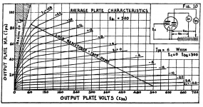
The datasheet sings the praises of this audio amplifier, but the obvious issue is the output impedance. Plate resistance is 24K. I think with a pentode input and two-stage feedback loop, the output impedance could be optimized for a 6.5K load.
Relatively simple and cheap to try, think it could be a fun little 4W amplifier and wouldn't cost me an arm and a leg to try out.
I now have a few time-consuming amplifiers in the pipeline and without a well-defined use for the LL9202, I was considering selling them to finance other parts. But I recently came across something that I think could be a fun, low-parts-count design to breadboard and potentially build if the results are good...
The 6B5 / 6N6G is an interesting dual dissimilar triode in which one half is wired as a cathode follower and internally direct-coupled to the second triode which is run as a 0V grid bias A2 power triode. You simply apply 300V, all biasing is done internally. Neat! The cathode follower provides A2 grid current to the output. Recommended load of 7K with 300V 42mA bias point, well suited for the 50mA 6.5K LL9202.
Here is an extensive application datasheet for the 6B5, 6N6G is the octal equivalent: https://frank.pocnet.net/sheets/201/6/6B5.pdf
And the characteristic curves with recommended 7K load line.

The datasheet sings the praises of this audio amplifier, but the obvious issue is the output impedance. Plate resistance is 24K. I think with a pentode input and two-stage feedback loop, the output impedance could be optimized for a 6.5K load.
Relatively simple and cheap to try, think it could be a fun little 4W amplifier and wouldn't cost me an arm and a leg to try out.
Last edited:
- Home
- Amplifiers
- Tubes / Valves
- Single Ended Output Tube for Lundahl LL9202 50mA