Interesting.. I should probably check it out 🙂 although I might need a little help with that as it doesn't look like a simple RC filter.
With regard to value selection, I was going on that post #169:
With regard to value selection, I was going on that post #169:
Remaining stock from motherboard recapping projects (often 3300µ/6.3V) should also work well.
Last edited:
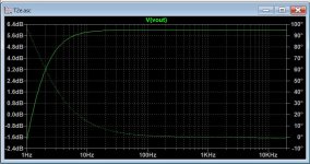
I ran a decade sweep in LTSpice using a .step param command for different values of capacitor across the 3 diodes but it did not show any difference in the frequency response:

I'm probably doing something wrong, but I usually get a reasonable approximation.
I'm probably doing something wrong, but I usually get a reasonable approximation.
Attachments
Mas Indra,
Many thanks for de Lima's white paper.
Very interesting; more psychoacoustic than engineering........
Tom,
We seem to have a low THD v. zero fb camp here, or at least, different points on the spectrum. For fifty years this spectrum has existed and people have taken opposed views. It is now a religion, and not likely to change - this is entertainment, after all.
Best to just agree to disagree, and designers to stay in their own threads?
Hugh
OK, this appears with high-Z load conditions, which is logical.True that.
I've attached my measurement of the T2 at turn-on and turn-off.
Increasing C73 to 22µF should help a lot, and solve this issue for 32 ohm (for 600ohm, that is less certain).
It also depends on the setting of R73.
More worrying is the turn-off thump, which looks nastier.
It will definitely be necessary to pass through the sim
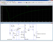
You won't see any difference like that, as overall FR is determined by global negative feedback. You would see a difference in THD(f) / IMD(f). Plot the voltage drop across the diodes instead.I ran a decade sweep in LTSpice using a .step param command for different values of capacitor across the 3 diodes but it did not show any difference in the frequency response:

I'm probably doing something wrong, but I usually get a reasonable approximation.
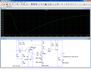
Hmm, it seems the effect at mid-high frequencies is eventually limited by power supply impedance, which is effectively in series with the diodes as well. This can be addressed by providing healthy capacitance across the rail. However, it seems that even 2200µ + 2200µ may only be about as effective as 1000µ across the rail + 1000µ from MOSFET source to ground. Whether you prefer 2200µ/35V + 2200µ/6.3V or 1000µ/35V + 1000µ/25V may be a matter of taste and power supply stiffness.
Last edited:
Several members in Pass forum investigated H2 distortion cancellation mechanism. I am not sure if Mark is aware but the T2 has the correct H2 phase to cancel some distortion of dynamic headphones.... de Lima's white paper. Very interesting; more psychoacoustic than engineering........
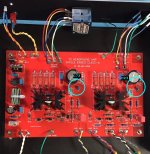
For those who want to experiment with changing the bias string bypass capacitor (C23 / C73), I have good news: there's quite a bit of empty space on the PCB in that vicinity.
A quick measurement on the PCB suggests you could just barely fit a 25 volt, 3300 microfarad (!) radial electrolytic capacitor in that zone. The Panasonic EEU-HD1E332B is 25mm long {same as the MOSFET heatsink} and 12.5mm diameter. You could mount it upside down and then bend the leads to fit into the existing drill holes.
This is not a recommendation, merely an observation: C23 and C73 have plenty of wide-open space nearby.
_
Attachments
I only have my volume pot left to hook up so hopefully tomorrow will be up and running.
Think I will wait and see what the collective pros come up with that's most beneficial modification wise before I change anything from stock.
Following the ddiscussion with interest even if nearly all the technical jargon is way over my head.
Think I will wait and see what the collective pros come up with that's most beneficial modification wise before I change anything from stock.
Following the ddiscussion with interest even if nearly all the technical jargon is way over my head.
I only have my volume pot left to hook up so hopefully tomorrow will be up and running.
Think I will wait and see what the collective pros come up with that's most beneficial modification wise before I change anything from stock.
Following the ddiscussion with interest even if nearly all the technical jargon is way over my head.
Muting circuit in my opinion would be most beneficial. I am currently making a PCB based on Pete milletts implementation which is quite robust.
Muting circuit in my opinion would be most beneficial. I am currently making a PCB based on Pete milletts implementation which is quite robust.
Sounds interesting Gareth do you think it might fit in the galaxy enclosure?
I never ever leave my headphones plugged in as have small children in the house who find such temptations within reach irresistible. However it would be good to retrofit a effective solution just to be on the safe side.
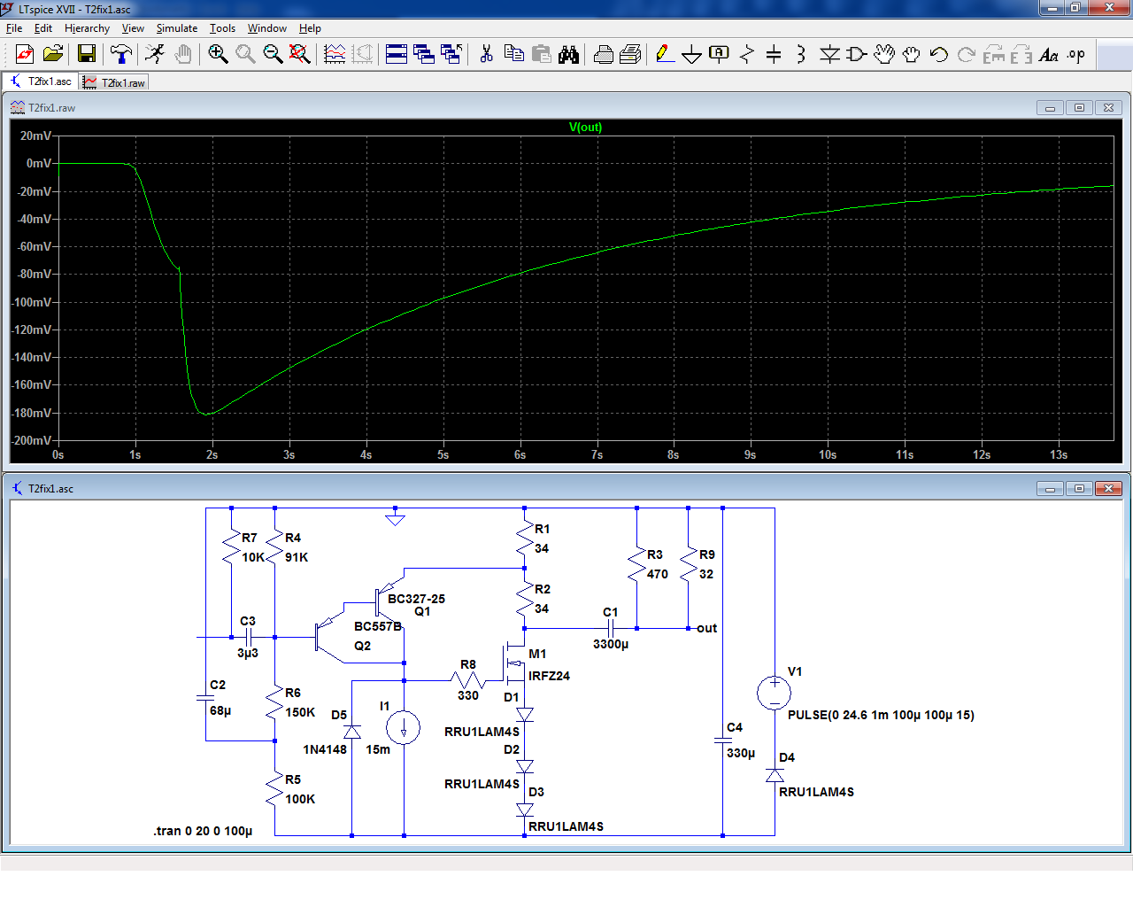
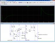
I have made a simplified simulation circuit.
The turn-on/off behavior is quite realistic:
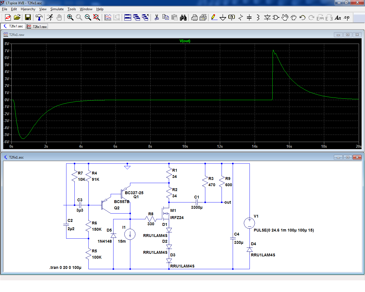
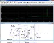
Let's concentrate on the turn-on first (the easiest).
If C2 is increased to 68µF, the thump becomes gentle, and completely subsonic:
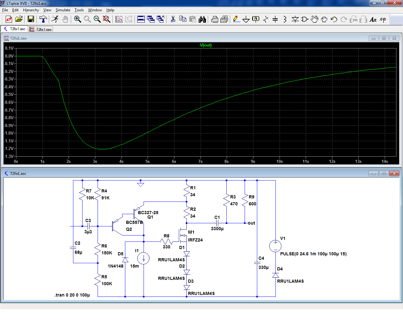
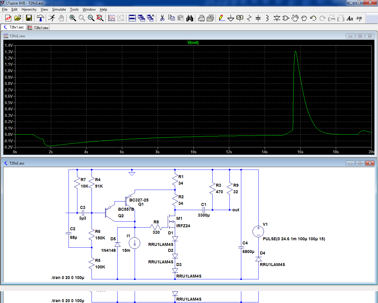
With a more common 32 ohm load, it becomes completely negligible:
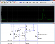
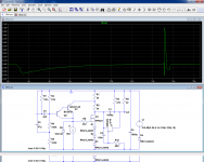
The turn-off problem is more difficult.
A possible solution uses brute-force: increase the bypass cap to very large values.
With a 600ohm load, the improvement is marginal:
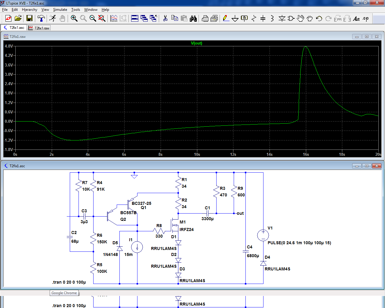
With 32 ohm, it becomes more acceptable:
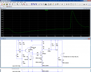
A smarter method is to use a depletion device to discharge the output cap.
I have used jFets (8 in //), for simulation purpose, but in reality a depletion MosFet should be used, with a suitable gate divider.
The RC used with the Fet is because the Vto is not ideal, but with a MOS, it should not be necessary.
With 600 ohm, a significant but relatively harmless residue remains:
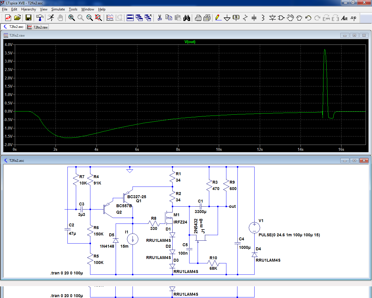
With 32 ohm, it becomes acceptable:
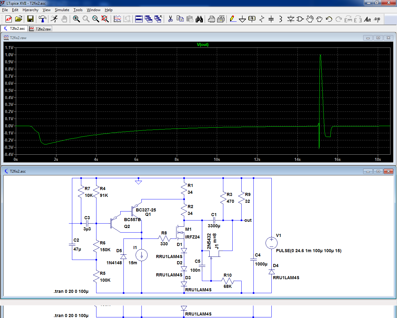
These fixes are not perfect, and cannot match a properly driven mute relay, but they can be implemented relatively easily on an existing circuit without butchering it: they are at most additive.
Note that a mute relay should react in the millisecond following the turn-off, because the phenomenon is fast and brutal
The turn-on/off behavior is quite realistic:
Let's concentrate on the turn-on first (the easiest).
If C2 is increased to 68µF, the thump becomes gentle, and completely subsonic:
With a more common 32 ohm load, it becomes completely negligible:
The turn-off problem is more difficult.
A possible solution uses brute-force: increase the bypass cap to very large values.
With a 600ohm load, the improvement is marginal:
With 32 ohm, it becomes more acceptable:
A smarter method is to use a depletion device to discharge the output cap.
I have used jFets (8 in //), for simulation purpose, but in reality a depletion MosFet should be used, with a suitable gate divider.
The RC used with the Fet is because the Vto is not ideal, but with a MOS, it should not be necessary.
With 600 ohm, a significant but relatively harmless residue remains:
With 32 ohm, it becomes acceptable:
These fixes are not perfect, and cannot match a properly driven mute relay, but they can be implemented relatively easily on an existing circuit without butchering it: they are at most additive.
Note that a mute relay should react in the millisecond following the turn-off, because the phenomenon is fast and brutal
Attachments
Make the worst-case conservative assumption of 200mA per channel drawn from the supply. Then the capacitor differential equation tells you the waveshape of the supply node when power is cut off. Since we are switching at the DC output of the SMPS (not at its AC input), whatever filter capacitors it might contain, do not participate in the turn-off event.
As far as I know, nobody has experimented with increasing the size of the NEGPWR bypass capacitor "C4" beyond 330uF. Whether that does, or does not, put the SMPS into "shutdown" due to excess inrush, is also not presently known.
_
As far as I know, nobody has experimented with increasing the size of the NEGPWR bypass capacitor "C4" beyond 330uF. Whether that does, or does not, put the SMPS into "shutdown" due to excess inrush, is also not presently known.
_
Last edited:
Elve,
When you talk about a mute relay, is this a discrete device or a relay with some external circuitry as well to set the delay ?
Wondering if there is a simple time delay relay that can be used here off of the 24vdc?
Alex
When you talk about a mute relay, is this a discrete device or a relay with some external circuitry as well to set the delay ?
Wondering if there is a simple time delay relay that can be used here off of the 24vdc?
Alex
I have made a simplified simulation circuit.
The turn-on/off behavior is quite realistic:
Love it when simulation matches reality that well! Thanks for running the sim.
If C2 is increased to 68µF, the thump becomes gentle, and completely subsonic:
Very nice!
Note that a mute relay should react in the millisecond following the turn-off, because the phenomenon is fast and brutal
One way to do that would be to add a diode in series with the supply, before the reservoir/bypass cap. Then take the supply for the output relay on the 'outside' of the diode, i.e. from the raw supply.
You might be able to use the voltage across C2 to drive the turn-on delay for your output relay. In that case, your output relay circuit becomes a relay, a diode, a free-wheeling diode for the relay, and a MOSFET driver. Maybe with a resistive divider to control the timing.
Tom
Sounds interesting Gareth do you think it might fit in the galaxy enclosure?
I never ever leave my headphones plugged in as have small children in the house who find such temptations within reach irresistible. However it would be good to retrofit a effective solution just to be on the safe side.
Shouldnt be a problem as the muting boards are quite small. I am the opposite, I dont like the idea of having to unplug my headphones when switching an amp on or off as I feel this should be a standard part of any design.
Member
Joined 2009
Paid Member
My solution to make a fast turn off is an emitter follower with a zener diode in the base. I didn't see it anywhere before but that's not to say I'm the only person to have devised this approach. The emitter follower sits in the power rail (collector to psu and emitter to the circuit under power such as an output relay). A zener diode with series resistor is placed between the base and ground. When the amp is powered up the reverse current flow through the zener provides the base current to the transistor and the circuit (e.g. relay) is powered up. The zener voltage is rated to a few volts below the normal operating voltage of the power rail. On turn off, when the supply voltage drops, the zener cuts out, starving the transistor of base current, turning off supply to the circuit. Works like a charm. In my project the full circuit under power is a SS relay with dc-detection and delayed turn-on but for this thread where turn-on is not an issue and dc-protection not required you might only need the pass transistor and zener + resistor. Zener diode noise may be a concern for T2, but I leave that to others to ponder.
TGM8 - an amplifier based on Rod Elliot P3a
TGM8 - an amplifier based on Rod Elliot P3a
Last edited:
Bigun, I think you meant that you tie the emitter to PSU and the collector to the load. That's the way you have it in the schematic in the TGM8 thread, and makes more sense from a base current POV.
Member
Joined 2009
Paid Member
Yes, thanks 'rco3', that's what I meant. You would make a valuable employee, being able to read the bosses mind 😀
My solution to make a fast turn off is an emitter follower with a zener diode in the base.
That's a clever trick. Parasound does something similar in their A23. I use it too.
If you really want the relay to turn off in a hurry, add a zener in series with the free-wheeling diode across the relay coil. This allows the flyback voltage to reach more than a single diode drop, which causes the relay to de-energize faster.
Tom
To put things in perspective, here are the results of a surge on a real VC.
Fast DC protection for HPamps.
I certainly do not advise going to the limits, but the effect of a limited thump on headphones is probably going to be benign.
I would be more concerned about the eardrums in fact: the turn-off event looks rather nasty, and with efficient HP, it could be problematic
Fast DC protection for HPamps.
I certainly do not advise going to the limits, but the effect of a limited thump on headphones is probably going to be benign.
I would be more concerned about the eardrums in fact: the turn-off event looks rather nasty, and with efficient HP, it could be problematic
- Status
- Not open for further replies.
- Home
- Amplifiers
- Headphone Systems
- Single ended class-A headphone amp using two transistors: T2