Sorry Tom, I have to disagree. Low distortion amp will preserve driver acoustic distortion while a carefully designed amp will cancel some of the driver acoustic distortion.
In theory, that certainly is possible. Perfect cancellation, would require for the distortion of the amp to be exactly 180º out of phase with the distortion of the driver and be of equal magnitude. That's rather improbable. Also, if you miss by even a little (in either phase or amplitude) you end up increasing the distortion.
Other method such as current sense feedback rarely used also reduce acoustic distortion.
Apologize for uttering the M-word here, but do you have measurements for this by any chance? If the distortion is being reduced, it should be possible to measure the reduction. It would be interesting to see how much reduction could be expected from such a feedback scheme.
Another approach could be to use a dual voice coil speaker to provide feedback from the speaker cone directly. I know that's been done, but I don't know what the results were.
Two of my friends in college used a piezo element to sense the acceleration of the speaker cone (on a KEF B139, which conveniently has a flat "cone"). They ran into a lot of trouble with stability. I forget if they actually made it work. Interesting idea, though. I seem to recall that their plan was to compensate for the driver rolloff, but it could potentially reduce distortion as well.
Your stated preference to low distortion amp indirectly shows your preference to the native acoustic distortion of the driver.
Possibly. I also tend to prefer low-distortion drivers. Let me know if you notice a trend here. 🙂
Tom
Last edited:
It is rather naive to expect anything perfect. Eduardo de Lima published a Whysingle-endedtubeamplifiers.pdf and this "Triodity" to cancel loudspeaker distortion is just an example of recent explorations.In theory, that certainly is possible...
Old hat stuff, RN Marsh published in Audio Amateur 1985 Marsh MFB ckt.pdf and Marsh MFB_2.pdf.... Apologize for uttering the M-word here, but do you have measurements for this by any chance? ...
Such as Electrostatics or Purifi driver? 😉Possibly. I also tend to prefer low-distortion drivers...
I think a responsible designer should take a closer look to the important matter, the actual acoustic output. Distortion of amplifier output voltage does not correlate linearly with acoustic distortion. A responsible review should show acoustic distortion measurement.
Good to see this thing getting back to what this threas is all about the T2.
It would be nice in a positive way if you could bring to the table things that you might change or modify in the T2 to make it more like somthing you think it should be?
Then us DIY'er could try and test etc and maybe learn somthing?
Alex
It would be nice in a positive way if you could bring to the table things that you might change or modify in the T2 to make it more like somthing you think it should be?
Then us DIY'er could try and test etc and maybe learn somthing?
Alex
Good to see this thing getting back to what this threas is all about the T2.
It would be nice in a positive way if you could bring to the table things that you might change or modify in the T2 to make it more like somthing you think it should be?
Then us DIY'er could try and test etc and maybe learn somthing?
Alex
I remember reading cant remember if it was here or on headfi that the power supply filter didn't filter correctly, hence why when some folk removed the 11 wraps ferrite core and just bridged the circuit with a wire noticed no difference. I would think a CRCRC filter would do very well in this circuit.
I am going to get KiCad up and running and produce a schematic for testing with the modifications that some users have mentioned. I would also implement a muting circuit to eliminate that thump too. Would be interesting to see the overall results. 🙂
Would using a different power supply vs the switching one go around all this?
Alex
That's what I have done and I've no doubt it can remove the mains harmonics and their intermodulation products that proliferate one of Toms graphs. I didn't find it detracted from the essence of the T2 sound that I like and it certainly brings subjective improvements. It is however a great deal more costly, i.e. regulator, filter, transformer and case, and for full benefit required taking the ferrite based filter out of circuit.
It also rather upsets the balance of the design, rather like putting a big heavy and powerful engine into a neat 1970's Mini.
In a very Nelson Pass way in its simplicity the T2 achieves something none of my other four headphone amps manage.
I am going to get KiCad up and running and produce a schematic for testing with the modifications that some users have mentioned.
The modification mentioned in post #215, might turn out to increase your enjoyment of the sound. Also take a quick glance at post #240.
John would you post a pix of your constant current mod so I can get an idea of where and how you installed it on the board?
Thanks
Alex
Thanks
Alex
Good to see this thing getting back to what this threas is all about the T2.
Agreed.
It would be nice in a positive way if you could bring to the table things that you might change or modify in the T2 to make it more like somthing you think it should be?
I'm guessing that's directed at me. Fair enough. Thanks. Please allow me to elaborate:
As mentioned in my review, I have two major concerns regarding the T2:
- Turn on/off thump
- Ringing (stability?) with capacitive load
These would be at the top of my list to deal with.
The turn on/off thump could be dealt with by a relay or with a MOSFET-based solution. A pair of large MOS devices with a photovoltaic driver would work. As would a well-chosen small signal relay. The amp should not be allowed to output 6-7 V peak when turned on or off as that puts the user's headphones at risk.
The T2 shows a lot of ringing on the transient response with capacitive loads. You see evidence of this even with 470 pF || 300 Ω and it gets worse as the capacitance is increased. In my view, this is problematic as these capacitances represent common cable capacitances.
There are likely several ways to address this. I'd defer to Mark for advice there as he knows his circuit best.
Lower on the priority list, you'll find:
- Ultrasonic noise, presumably from the SMPS, appears on the output
I put that lower on the list as it's more of a "technical eyesore" than an issue (unless you're able to hear 50 kHz, that is). Still, Mark went through the trouble of including a supply filter, so I think it's reasonable that this filter should work well. I would suggest finding a shielded, leaded inductor with an inductance that - along with the supply capacitance - provides meaningful attenuation of the switching frequency of the SMPS without resulting in peaking. I further suggest validating the implemented filter by measuring the ultrasonic output of the T2 after a new filter has been implemented. This can be accomplished by anyone with a sound card capable of sampling at >120 kHz.
On the mechanical side of things you'll find:
- Hole missing for locking tab on power switch washer
- Grounding wires causes front and rear panels to bow
I suggest adding a hole for the locking tab on the washer for the power switch. The washer is intended to prevent rotation of the switch as it's operated. Basically, it keeps the switch aligned and prevents it from rattling loose. Anyone who's ever used those switches will know the presence of this locking tab ... as they've at one point forgotten to drill the hole for it. I know I have. 🙂
Rather than grounding the front/rear panels by a solder lug, I'd consider adding a solder pad on the front/rear panels (which are PCBs) so you can just solder a ground wire to that. Or better yet, a grounding lug could be added in the chassis somewhere so you don't have to rely on the connection to the front/rear panels for the ground connection.
Some may argue that I'm picking nits. And maybe I am. But considering that this kit will be available through the DIY Audio Store, hence, has the potential of affecting the reputation of DIY Audio, I think it's prudent to make the kit as high quality as possible. It should work as well as possible out of the box. This is my view. Others are free to disagree.
Then us DIY'er could try and test etc and maybe learn somthing?
And maybe have fun too? 🙂 That should be part of it as well. Otherwise, why bother?
Tom
Last edited:
Reference to post #169 and using a cap to bypass the three diodes D72, D73 and D74. What exactly would this impact be to the sonic signature?
It was mentioned that:
"Turns out there is in fact a significant increase in loop gain and corresponding reduction in distortion with the extra bypass cap - about 14 dB in sim." this was in post #169.
Just trying to understand how this translates into a better "output" that I might hear?
...and yes I have two 4700uf on their way here...to test.
Alex
Tom,
I like the idea of using a small signal relay for muting on/off. I used these in several other builds with a 3 sec delay. Panasonic DS2E-S-DC24V. I think I got them from mouser, and they are getting expensive and the last time I looked (months) they were on a long backorder.
The issue my pea brain has is figruing out how to make the connections on the board so its done right and neatly. I guess this is part of the "fun"!!
One person that has built the T2 told me he has no trun on or off thump? and suggested I try plugging in the power adapter to a wall switched ac plug?
Alex
Ok this is my third post in a few mintues, apologize for that, but I spent this morning using the Beyer T1's and now Beyer T90's with the T2. The presentation has been as I have reported before is nothing but Stellar....seriously good.
I have spent the last few days with new Focal Clears on a good SS amp, and a Bottlehead Mainline amp...again Stellar performance all around.
The T90s are very bright, sharp and any distortion etc should IMO be readily apparent and its not for me.
Same holds true for the Focal Clears. The only thing I might be hearing is the bass on the 55 ohm Focals might be abit "loose" or "less controlled"...
So I am wondering not about why the measurements are valid or not, I am wondering about the sonic changes when you use different headphones with widely varying impedances has on the end result.
The T1 are 600 ohms, the T90s 250 ohms and the Focals are 55 ohms...
I like the Focals more on other amps than I do with the Beyers mentioned on the T2.
So is there some magic going on here?
Alex
Member
Joined 2009
Paid Member
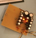
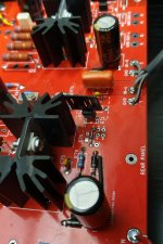
Here's my version of the T2
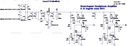
I just remembered that I built a headphone amplifier with such a current source, only my 'CFP' output was without gain. The topology was inspired by Naim. I put all the details here: Grasshopper
So it seems that I made a 'T2' kind of thing and now I'm a fully signed up member of the club 😀
I can't say if the current source helps or hinders the sound because I didn't compare with and without - unfortunately my headphones were a bad fit to my hearing so I sold them
Here's something I tried a few days ago on the T2. It is a current source...
I just remembered that I built a headphone amplifier with such a current source, only my 'CFP' output was without gain. The topology was inspired by Naim. I put all the details here: Grasshopper
So it seems that I made a 'T2' kind of thing and now I'm a fully signed up member of the club 😀
I can't say if the current source helps or hinders the sound because I didn't compare with and without - unfortunately my headphones were a bad fit to my hearing so I sold them
Attachments
Last edited:
A quick inspection of the schematic doesn't show an obvious reason for the turn-on thump (I leave the turn-off aside for the moment, because the situation could be less clear).
Here is the schematic, as a basis for the reasoning:
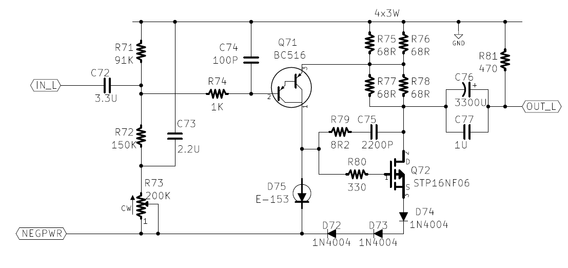
When the power is absent, capacitors C72, 73 and 76 are discharged. (for C72 this also depends on the upstream circuit, but the end result is the same, its right armature sits at the GND potential)
At the instant the power is applied, Q71 will thus be off, and Q72 will follow, meaning no current will flow through R75-78.
Thus, no thump at this stage (in principle)
Then, C72 and 73 will begin to charge relatively slowly, making Q71 to conduct, and at some point, the conduction will be sufficient to overcome D75, causing the conduction of Q72.
As soon as Q72 conducts, the FB loop will become active, and the emitter of Q71 will follow its base, ie. slowly going more negative.
The drain of Q72 will thus go negative at a rate governed by the time constants of C73/R73 and C72/R71//72.
Since they are larger than the output time constant (with a 32 ohm load anyway), the disturbances should remain relatively minor.
If some conditions are met, namely R73 turned heavily CW, open input and high impedance HP, the thump could be present at this stage.
This could be fixed by increasing massively C73, to 22µF for example.
The startup time would still remain acceptable, and the possible thump should be gone.
This is a purely theoretical analyzis; I didn't make any sim, and I could have missed something.
Mark probably has the circuit in sim (a simplified version is quite sufficient).
Maybe he could post it, to check exactly where the problem lies, and identify possible fixes
Here is the schematic, as a basis for the reasoning:
When the power is absent, capacitors C72, 73 and 76 are discharged. (for C72 this also depends on the upstream circuit, but the end result is the same, its right armature sits at the GND potential)
At the instant the power is applied, Q71 will thus be off, and Q72 will follow, meaning no current will flow through R75-78.
Thus, no thump at this stage (in principle)
Then, C72 and 73 will begin to charge relatively slowly, making Q71 to conduct, and at some point, the conduction will be sufficient to overcome D75, causing the conduction of Q72.
As soon as Q72 conducts, the FB loop will become active, and the emitter of Q71 will follow its base, ie. slowly going more negative.
The drain of Q72 will thus go negative at a rate governed by the time constants of C73/R73 and C72/R71//72.
Since they are larger than the output time constant (with a 32 ohm load anyway), the disturbances should remain relatively minor.
If some conditions are met, namely R73 turned heavily CW, open input and high impedance HP, the thump could be present at this stage.
This could be fixed by increasing massively C73, to 22µF for example.
The startup time would still remain acceptable, and the possible thump should be gone.
This is a purely theoretical analyzis; I didn't make any sim, and I could have missed something.
Mark probably has the circuit in sim (a simplified version is quite sufficient).
Maybe he could post it, to check exactly where the problem lies, and identify possible fixes
I get no turn-on thump with the T2. Granted I never turn on a headamp with phones on, so maybe there is a very low volume thump - but nothing audible before I put them on.
A quick inspection of the schematic doesn't show an obvious reason for the turn-on thump (I leave the turn-off aside for the moment, because the situation could be less clear).
I disagree. I think the thump source is painfully obvious in the schematic: It's the output cap. The output cap needs to charge to roughly VCC/2. This requires charge to flow into the capacitor. That charge flows through 470 Ω (R81) in parallel with your phones. That causes the thump.
You can measure it easily with an oscilloscope.
This is a known issue with single-ended designs. The Schiit Asgard had the same issue and Schiit took appropriate corrective action and added an output relay.
Tom
Last edited:
It certainly does; what matters is the time taken to do soThe output cap needs to charge to roughly VCC/2.
If the voltage on the drain of Q72 rises slowly enough, the thump will be mild and subsonic (thus not noticeable).This requires charge to flow into the capacitor.
That charge flows through 470 Ω (R81) in parallel with your phones. That causes the thump.
I don't have have the circuit handy, and I cannot duplicate the test, but I have no reason to doubt your assertion.You can measure it easily with an oscilloscope.
The question is why this behavior is observed: if the conditions I enumerated are met, the thump will be present.
Under less extreme conditions, the thump should be minor, or quasi-absent (based on my analysis anyway -could be flawed-).
If Mark posts the sim circuit, the hypothesis can be explored in more details (it could also be done in the old-fashioned manner, but it takes more time, and a human can also make wrong assumptions, something a neutral and "dumb" software is immune to).
Note that I am not taking sides in this controversy, I just try to find as objectively as possible what is going on: I felt that the thump shouldn't be there, at least in the majority of the cases, if it is present, I would like to know precisely why.
If the voltage on the drain of Q72 rises slowly enough, the thump will be mild and subsonic (thus not noticeable).
True that.
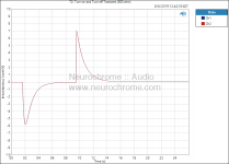
I've attached my measurement of the T2 at turn-on and turn-off. The measurement clearly shows the turn-on and turn-off transients, i.e. the instantaneous voltage applied to your headphones when you turn on/off the T2 with the 'phones connected.
Whether you consider them to be an issue is entirely up to you. I wouldn't personally release a circuit that produced those thumps, but that's me. Others are free to have different standards.
As many have pointed out, this is DIY, so if you take issue with the thumps, you can always design an output muting circuit.
Tom
Attachments
Last edited:
Reference to post #169 and using a cap to bypass the three diodes D72, D73 and D74. What exactly would this impact be to the sonic signature?
It was mentioned that:
"Turns out there is in fact a significant increase in loop gain and corresponding reduction in distortion with the extra bypass cap - about 14 dB in sim." this was in post #169.
Just trying to understand how this translates into a better "output" that I might hear?
...and yes I have two 4700uf on their way here...to test.
Alex
I installed a couple of 3300uF 10V caps in those positions about 6 weeks ago.
I honestly can't say that I could hear a difference between having the caps and not - I never carried out any A/B testing. But that said, I left them in because I did not feel they were detrimental.
I get no turn-on thump with the T2. Granted I never turn on a headamp with phones on, so maybe there is a very low volume thump - but nothing audible before I put them on.
I also don't recall experiencing any turn on thump with this one. I'll double check when I get home though.
Attachments

Last edited:
If you're not careful when choosing the capacitor value, you can accidentally put the corner frequency in the (audible) high bass region. Which will ruin the response in the low bass. Draw it up on the chalkboard and write some equations.
- Status
- Not open for further replies.
- Home
- Amplifiers
- Headphone Systems
- Single ended class-A headphone amp using two transistors: T2