I gently suggest you read post #349 again. It proposes an experiment which is relatively easy to perform. The experiment does not add any new PCBs either inside or outside the chassis, does not add or remove any components on the existing PCB, does not require drilling any holes in the PCB or chassis, and adds only a single $5.50 (qty=1) new component.
_
_
Last edited:
I gently suggest you read post #349 again. It proposes an experiment which is relatively easy to perform. The experiment does not add any new PCBs either inside or outside the chassis, does not add or remove any components on the existing PCB, does not require drilling any holes in the PCB or chassis, and adds only a single $5.50 (qty=1) new component.
I missed Bigun's post amidst the rest of the discussion. Seems perfectly reasonable.
My T2 joins the collection today.
A big thank you to Mark Johnson for sharing his design and pcbs and all those that have offered kind words of wisdom on the diyaudio thread.
I needed to make a slightly a different front panel only to make use of a course and fine 36 step attenuator that's been sat in my parts box for a few years in place of the blue Alps specified.
PS a 1meter length of cat 6 cable is sufficient to complete the 11 turns on the ferrite as well as providing enough wiring for hooking up.
First impressions
Its sounding very nice hooked up to my Oppo 205 dac and streaming via Roon Rock.
I've been listening with Oppo pm3 and Sennheiser HD800 (sdr mod)
JamieMcC, that's a beautiful build. Congratulations!
The black faceplate with its carbon-fibre texture, might be an extremely good pairing with silver volume control knobs. See whether any of these sings to you:
1pcs 30mmx16mm SOLID Aluminum Home Vintage Amplifier Audio Rotary VOLUME KNOB 6183500593686 | eBay
30*26mm Silver Aluminum Car audio amplifier volume Knob High end CNC machined*2 | eBay
CUSTOM KNOBS 30MM QTY-1 ALUMINUM TUBE AMPLIFIER AMP PREAMP MACHINED AUDIO HIFI | eBay
Or we could just emphasize taking off headphones prior to turning on/off, which I think we would all agree is best practice anyway?
I tried explaining to the wife The Operating Procedure and could see her eyes glaze over.
Point is, usage should be easy and intuitive, and there should not be risk of damage to the headphones.
Bigun's idea of using a DPDT power switch and simultaneously cutting the output line should do the job.
Presumably you implement a switched ground on the headphones?
Thanks Mark, Alex
Yes was thinking the same thing myself about the silver knobs and ordered some of these at the weekend but they will take a while to arrive on the slow boat from China.
2x 30mmx22mm Aluminum STEREO Hi-Fi VOLUME CONTROL KNOB 812854369697 | eBay
A 1mm carbon fibre veneer is glued on to the front panel that came with the Galaxy case I have a few bits left over made for other projects.
When my new led arrives I plan to replace the captive nut and bolt method of fixing the top and bottom panels with either self tapping screws or tap and fit machine screws. This should give good continuity between all faces of the enclosure without using the lugs on the front and rear panels and also make removing and replacing the top easier.
My T2 is silent at full volume (no music playing) the turn on thump experienced which I am surprised at after the comments here is actually pretty low level with the 32 Ohm 250 Ohm and 300 ohm headphones tried, certainly not at an audible level that would cause concern.
Anyone have a part number for a multiple contact switch that would work?
I am assuming three things need to be connected to this switch, power and the L.R sigs?
Alex
I am assuming three things need to be connected to this switch, power and the L.R sigs?
Alex
Perhaps you're thinking of something along the lines of this part# at Mouser? It ends with an "H" so you get lockwashers and mounting nuts in the package.
_
In my opinion its good for eliminating the thump when turned off but would do nothing to eliminate the turn on thump as when the switch is flipped it will at the same time as powering on connect the headphones back up. Plus it would make the wiring look sloppy trailing extra wires back and forth. It would be far more elegant to use a proper circuit. But that's just me being picky. 🙂
I believe someone posted a proposal which, they said, completely eliminates the turn-on thump in simulation. But does nothing about turn-off. If I remember correctly it was a change to a component value, i.e., unsolder one component in each channel, and solder a replacement back into the same holes. No drilling, no cutting of traces, no jumper wires, no additional PCBs.
.... I cannot go further without using more accurate simulation models, it would be wasted
Patrick posted some models early on: Single ended class-A headphone amp using two transistors: T2
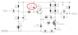
Back in post 331 Elvee stated the value of C2 in his simulation if increased to 68uf would kill the turn on thump.
This is C23, C73 in Marks schematic. These are 2.2 uf caps.
I found this 68Uf at Mouser:
But its only 6.3 v rated. Would this work?
Its a MLCC Leaded, the existing ones are Murata at 50v.
Two of these would be only approx $2 + shipping throw in the $5.00 switch...
Alex
This is C23, C73 in Marks schematic. These are 2.2 uf caps.
I found this 68Uf at Mouser:
But its only 6.3 v rated. Would this work?
Its a MLCC Leaded, the existing ones are Murata at 50v.
Two of these would be only approx $2 + shipping throw in the $5.00 switch...
Alex
My sim shows that cap exposed to around -15v
This is assuming a mid-point value of R73.
Basically it is a 3 resistor potential divider formed by R71 (91k), R72 (150K) and R73 (0-200k). It will be between -22 and -12v depending on the setting of R73.
This is assuming a mid-point value of R73.
Basically it is a 3 resistor potential divider formed by R71 (91k), R72 (150K) and R73 (0-200k). It will be between -22 and -12v depending on the setting of R73.
Attachments
Last edited:
C23 needs to be rated for 25V or higher. Here are several 68uF and higher caps, with 25V rating and 5mm lead spacing, that are in stock & on the shelf at DigiKey, maybe one of them might be what you are looking for?
Aluminum Electrolytic Capacitors | Capacitors | DigiKey
(I don't know how long they keep these links alive and working on their website -- probably not "forever")
_
Aluminum Electrolytic Capacitors | Capacitors | DigiKey
(I don't know how long they keep these links alive and working on their website -- probably not "forever")
_
Attachments
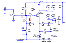
Nicely done![the voltage across capacitor C73] is a 3 resistor potential divider formed by R71 (91k), R72 (150K) and R73 (0-200k). It will be between -22 and -12v depending on the setting of R73.
If you wanted to, you could set R73 to whatever numerical value is required in simulation, to get a voltage drop of 5.10 volts across R77. I.e. perform the biasing procedure in simulation.
Mark
Thanks for the link to the 68uf cap, these are electrolytics, and the existing one is a non electrolytic....would this matter at all, except for getting the polarity right?
Parts on order, digikey even had the switch.
Alex
Thanks for the link to the 68uf cap, these are electrolytics, and the existing one is a non electrolytic....would this matter at all, except for getting the polarity right?
Parts on order, digikey even had the switch.
Alex
Last edited:
Member
Joined 2009
Paid Member
I typically use an electrolytic for power decoupling and I aim for one of the 'audio' targeted' caps
Aluminum Electrolytic Capacitors | Capacitors | DigiKey
Aluminum Electrolytic Capacitors | Capacitors | DigiKey
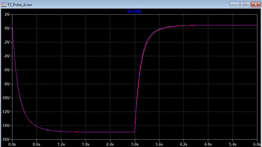
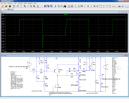
Unfortunately, the BC516 model provided is useless for large signal/transient purpose: I have tried to apply a 10kHz squarewave, but it goes completely berserk: it remains saturated for quite a time after a negative transition, creating a huge artifact: a large negative spikePatrick posted some models early on: Single ended class-A headphone amp using two transistors: T2
Attachments
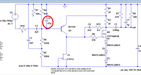
I thought you were going to increase the capacitance from BJT-base to the positive supply rail (GND)? Instead it has decreased .. ?? And the 1K series resistor has disappeared .. ??
You might want to check and verify that the static bias current Ids of the MOSFET is 150 milliamps. That's what the builder does when s/he adjusts the 25 turn trimmer potentiometer.
_
You might want to check and verify that the static bias current Ids of the MOSFET is 150 milliamps. That's what the builder does when s/he adjusts the 25 turn trimmer potentiometer.
_
Attachments
Last edited:
- Status
- Not open for further replies.
- Home
- Amplifiers
- Headphone Systems
- Single ended class-A headphone amp using two transistors: T2