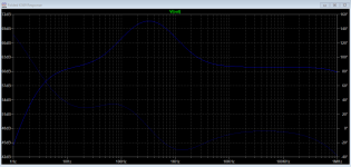
Hopefully, lets see. When C1 isn't in circuit you get a big bump at 1kHz. Such a scenario computes with your weird test figures.
While one channel tracks at all the settings, the other is way higher. at 40dB, the other is at 47dB. At 43dB setting, the other is at 51dB. At 56dB setting, the other is at 63dB.
Is there a possibility some value is wrong in the passive RIAA components in one channel and exaggerates 1kHz test signal with a response hump?
The bad joint on C1 thing explains your initial 7-8dB 1kHz bumps. See simulated response without C1 in circuit. When partially touching maybe moderates the bump's dB somewhat.
Attachments
Beautiful— thanks Salas — I resoldered C1 and I can no longer induce the trouble by jiggling it. Gonna keep it on the cooker all day and will monitor.
Here’s a pic of it with the new caps. As well as one of it next to the Valve Itch. I did a pretty robust shoot out between the two on Friday night, but I’m considering the results null and void since I hadn’t identified the issue with the one channel at that time. Even with the issue, the UFSP held its own, but the Valve Itch is very special. Once the UFSP gets burned in, I’ll do it again. 43 dB setting on the UFSP is nearly identical to the Itch.
Here’s a pic of it with the new caps. As well as one of it next to the Valve Itch. I did a pretty robust shoot out between the two on Friday night, but I’m considering the results null and void since I hadn’t identified the issue with the one channel at that time. Even with the issue, the UFSP held its own, but the Valve Itch is very special. Once the UFSP gets burned in, I’ll do it again. 43 dB setting on the UFSP is nearly identical to the Itch.
Attachments
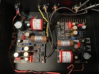

Surely listen to them again. If C1 was already intermittent its a big null. Valve Itch was made soon after the initial simplistic in an attempt to match its quality level but for triode sound. Its very good. Serious difference is its a more expensive hot and cautious build. With its film caps loaded HV shunt reg, heater PSUs extra transformers, and especially if with first rate sought after output stage tubes like Melz 1578 the BOM hurts. Another thing is it needs some good SUT for MC. Expenses again. UFSP does down to LoMC straight with lower hiss even.
Yes, and my Itch is stuffed with bulk foils, Shinkohs, NOS exotic caps, Mundorf Supremes, 1940s VT-231s...etc..no slouch.
Tubes are alluring and evoke the rare bottle$ collector's instinct... BTW prefer leaded eutectic solder wire for best forming and reliable joints. Setting the iron well over 300C is more secure especially when wide thick ground planes are involved like in the UFSP.
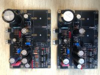
Yes — the ground plane on this board is robust! Highly recommend everyone turn up their irons and closely check their ground connections. I had trouble with a few of them, and of course it was the ground connection on C1 that wasn’t soldered properly.
Interesting. I had the same situation with my board. There were some solder connections that just sucked up the heat. I had to turn up the heat on the soldering iron. Looking back they were all ground connections. The ground plane must be quite robust, which explains why the preamp is so quiet even with out a chassis. My chassis has arrive, and hopefully I will start drilling today.
Stuffing question
I am on late stages of stuffing the new boards. First of all thanks to Salas and Tea for all they have done to bring this to us. Impossible task with out both of them. Thank you.
My question,
My SK369's have values of 13.66, 13.66, 13.73, 13.75. All 4 R2 and R3's have the same value. I am thinking the best way to lay it out is to put the .66's in the same position on the boards and the .73, .75's in the same position on the boards so that the channel match is best. Correct?
Thanks,
Don
I am thinking the best way to lay it out is to put the .66's in the same position on the boards and the .73, .75's in the same position on the boards so that the channel match is best. Correct?
Yes, that will be fine
Interesting. I had the same situation with my board. There were some solder connections that just sucked up the heat. I had to turn up the heat on the soldering iron. Looking back they were all ground connections. The ground plane must be quite robust, which explains why the preamp is so quiet even with out a chassis. My chassis has arrive, and hopefully I will start drilling today.
Yes, some work piece's difficult copper mass strains the iron's thermal capacity. Especially felt in repeat joints. Exactly like when discharging a capacitor with a heavier load. Not only higher temperature setting but tip choice plays a big role too. Wider shorter iron tips store more thermal energy steadier flowing to the piece allowing the soldering station's PSU finding time to replenish it.
43 dB setting on the UFSP is nearly identical to the Itch.
Use the 43dB for the HMC cart and the 40dB for the MM cart on the UFSP. Compensate their MM 3dB loudness difference with the volume control for A/B listening. Not to eat away overload space. The tube phono has fixed gain but huge overload margin due to its 300V rail so no worries for the higher than standard MM gain there. The tube unit is still in good native SNR territory for those two cart types, it won't need be intermediated by some SUT's quality factor yet. It still plays football with a home field advantage.
UFSP foto and test question
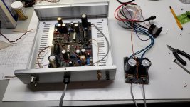
Fotos of mostly stuffed UFSP. Tested PS to see if it is ok to hook up when completed. Used bench supply set to 20V. When turned on, leds lit for a second then went out. Current went to 300mA for a couple seconds then to zero. DMM at output showed 20.3V. No smoke or sparks. M1and M2 stayed cool. As expected?
Ok to hook up when build is complete. Cautious noobie.
Thanks,
Don
PS, first pic post. Going to need it for help.😱
Attachments
Thanks. Bench supply only does 30VDC so I'll redo using the Suggested trafos and raw PS. Bought my cart today so I'm committed to the project.🙂
Don
Don
Which one cart model? If the bench supply is two channel you can configure them in series to double its max voltage (and halve its max current). If so read its manual carefully on series mode.
I noticed the heavy ground plane on the PCB when soldering too, definitely substantial and takes some heat to get a good joint.
I did more work on the case design, cleaned some dimensions up, added a masked hole for the chassis grounding (so it doesn't get powdercoated - same for the two lower lid screws so it's also grounded), some more markings on the back and rounded the ends of the vents on top for the shunt regulators.
The case is 350x200x80mm. DC cutout is for a Neutrik DLX series XLR jack which comes in 4 and 5 pin variety giving an option on the grounding method. The RCA holes are 10mm and fit the Rean isolated jacks (and probably a lot others). The ground is an isolated binding post from Cinch/Johnson. Any M3 screw secured feet should work, I found some at Mouser.


Here is the Protocase Designer file:
View attachment salas_ufsp_case-190720.zip
I did more work on the case design, cleaned some dimensions up, added a masked hole for the chassis grounding (so it doesn't get powdercoated - same for the two lower lid screws so it's also grounded), some more markings on the back and rounded the ends of the vents on top for the shunt regulators.
The case is 350x200x80mm. DC cutout is for a Neutrik DLX series XLR jack which comes in 4 and 5 pin variety giving an option on the grounding method. The RCA holes are 10mm and fit the Rean isolated jacks (and probably a lot others). The ground is an isolated binding post from Cinch/Johnson. Any M3 screw secured feet should work, I found some at Mouser.
Here is the Protocase Designer file:
View attachment salas_ufsp_case-190720.zip
- Home
- Source & Line
- Analogue Source
- Simplistic NJFET RIAA