Salas, thank you very much for the quick and detailed response.I looked in it using LTspice. Stability still safe, Zout curve compromised at LF & HF vs the original. I suggest: R42,R52 delete. R53,R44 2.2k. C23 10u.
Low voltage test is only to verify the CCS is regulating mA. Delete that extra 4.7k as it compromises the open loop gain severely.
Make sure R9 R10 are 68k and not 6.8K. Remove the Zener located near the JFET. Test. If still no good remove the JFET and the TO-126 BJTs to confirm them in a component tester or otherwise. Also turn the 1k trimmer with the Ohm meter connected across to make sure it spans its value normally.
Took out the 4.7k and reconnected the trace to normal. Checked n confirmed R9/R10 both are 68k. Zener removed. Confirmed the I k is in normal condition.
Q5 measure 366ohm n vary when 1k pot in different turns. Q4 sits in mohms n the 117 has been replaced with new ones .From the troubleshooting posts: "Another test tip is, as the circuit is off power, Q5 between E,B pins on Ohm meter with red probe on E should be reading in the hundreds of Ohm and changing reading when turning the R11 trimmer. When a blown Q5 could read a couple of Ohm near short. Q4 should be reading in the hundreds of kilo Ohm on same test probing (the trimmer is not involved in Q4)."
Power on with 260v 40 mA supply, led was on but still 10v at output. No response with turning the 1k. 🤔
Just checked. O voltage🤔Do the IRF840s show healthy Vgs like 4V or so?
Thus they don't shunt current. Either broken, or not insulated, or the CCS mA ain't enough and solely consumed by the load.
Salas, thanks again for the recommendations on using two IRF640 instead of IRF840. Everything works very well. In the final version, two IRFP240 were used.
You are welcome. Having a picture?
Attachments
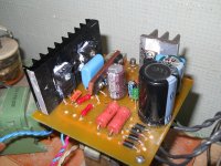
Yes, there are old Soviet parts. In a metal case jfet 2P303B.Do I see some Russian components? What is the little one in the metal can? A Jfet?
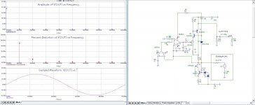
The stabilizer feeds the voltage amplifier with the input signal from the current output of the DAC, where R14 is the internal resistance of the DAC. The input resistance of the circuit is close to zero. The circuit can also work from voltage signals. To do this, we remove the input bias of 1.65v, install the R14 resistor with a resistance of 600-1000 Ohms and it will be a linear converter of the input voltage to current. The sound with the stabilizer has become noticeably cleaner, especially at low frequencies, the depth of the sound stage has increased.What you use this SSHV for? Sounding good?
Attachments
Hi Salas,
I managed to somehow short the output of an SSHV2. I’ve replaced all transistors apart from Q1 (I figured it would be the others), but still cannot set current or voltage using the trim pots. LED1 lights up okay. Before I hack into Q1, which other devices should I check? Of course, before the mishap everything was fine.
-Raja
Last edited:
Hi Salas,
Thanks for the quick reply.
Here‘s what I get:
Q1 = 1.506V
Q2 = 1.487V
CCS portion is actually working
However, something around Q3 is messed up downstream:
Q3 = 0V
Q4 = 0.487V
Q5 = 0.476V
all of these are “new’…. Any help appreciated.
Thanks for the quick reply.
Here‘s what I get:
Q1 = 1.506V
Q2 = 1.487V
CCS portion is actually working
However, something around Q3 is messed up downstream:
Q3 = 0V
Q4 = 0.487V
Q5 = 0.476V
all of these are “new’…. Any help appreciated.
Last edited:
If the dummy load is correct and does not overload the output, take out Q3 to check it on a component tester or otherwise. Without 3-4V Q3 Vgs the Q4 Q5 transistors will not bias up properly.
Okay, I will check it in the morning. I’m also wondering if any of the zener diodes could be dead due to the output being shorted (cause of original failure).
- Home
- Amplifiers
- Power Supplies
- Simplistic mosFET HV Shunt Regs