Yes, tested continuity between sink and drain I have open loopHas a nylon grommet for the screw too?
Attachments
correct, but I was aware of the error and correctly wired itCN2 on your board is wrongly labeled S0F when it should be F0S
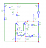
When we short F+ with F0 the whole shunt voltage regulating part is bypassed and we are able to test the Mosfet cascode CCS series part alone. Using safe low voltage. I don't see anything wrong there in your utilization, especially after your clarifications. Do you have a component tester? Checks OK all Mosfets you got?
Do you see an issue the amperage of the LV? It is 0.4A, anyway the Vin stays on a steady 9.3V
Only weird scenario I could think of is it has cable length inductance and/or switching noise and the cascode oscillates. 0.4A is enough because it would not pull much over 100mA from the source when set to max. Put a film capacitor across CN1 just in case.

Ok, I started from zero. I made the CCS on a breadboard with 2 new DN2540, working. Started a new board with only CCS without zeners and is working fine now. I just realized that 1.8R resistors I was using are out of tolerance, they measure 8-10R, I'll source new resistors and then keep populating the board.
Use 100R not 100K, R1 R2 are gate stoppers i.e. moderate value dampers, unless that was a typoI have R1 and R2 100K, are they ok?
Hi Salas, I'm almost there, the circuit is now regulating the output voltage, the only issue I have is the CCS output current. The preamp that I'm planning to build draws 8mA, but the CCS doesn't go below 10mA. Is this normal ?
Thank you and happy new year.
Thank you and happy new year.
SSHV2 needs 20mA spare current to works properly, so if you aim for 8mA do you have to set the CCS minimum for 28mA
I don't know right now, will have to simulate for phase margin etc. and let you know. IRF840 in guises like IRF840PBF / APBF isn't EOL and there are enough ~500V types for single N-MOSFET replacement tryouts. There is the problem with shortage of parts due to the worldwide disruption in silicon chips production too. At least the GB items are still secure for original semis stock as I see.
I looked in it using LTspice. Stability still safe, Zout curve compromised at LF & HF vs the original. I suggest: R42,R52 delete. R53,R44 2.2k. C23 10u.
Salas,
I move my questions over here from 6v6 thread.
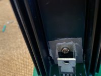
My sshv2 boards both are working with low 32.5v 40mA bench supply n I got 32v at output with 10k load. I then put it up with 250v supply also with 40mA n 10k load. The led is on but there is only 18/19v at 10k, the 1k trimmer doesn't work as plan. I did modify a bit on the board as shown in the picture to make it up to now. Thanks in advance.
Albert
I move my questions over here from 6v6 thread.
My sshv2 boards both are working with low 32.5v 40mA bench supply n I got 32v at output with 10k load. I then put it up with 250v supply also with 40mA n 10k load. The led is on but there is only 18/19v at 10k, the 1k trimmer doesn't work as plan. I did modify a bit on the board as shown in the picture to make it up to now. Thanks in advance.
Albert
Attachments
Low voltage test is only to verify the CCS is regulating mA. Delete that extra 4.7k as it compromises the open loop gain severely.
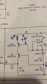
Make sure R9 R10 are 68k and not 6.8K. Remove the Zener located near the JFET. Test. If still no good remove the JFET and the TO-126 BJTs to confirm them in a component tester or otherwise. Also turn the 1k trimmer with the Ohm meter connected across to make sure it spans its value normally.
Make sure R9 R10 are 68k and not 6.8K. Remove the Zener located near the JFET. Test. If still no good remove the JFET and the TO-126 BJTs to confirm them in a component tester or otherwise. Also turn the 1k trimmer with the Ohm meter connected across to make sure it spans its value normally.
From the troubleshooting posts: "Another test tip is, as the circuit is off power, Q5 between E,B pins on Ohm meter with red probe on E should be reading in the hundreds of Ohm and changing reading when turning the R11 trimmer. When a blown Q5 could read a couple of Ohm near short. Q4 should be reading in the hundreds of kilo Ohm on same test probing (the trimmer is not involved in Q4)."
- Home
- Amplifiers
- Power Supplies
- Simplistic mosFET HV Shunt Regs