But you can adjust down? Try next value R9,R10 i.e. 27k, if still no good, 33k.
How you use the IXTP? As Q1 or in both positions? If not, what is your Q2?
Measure Vgs for Q1 and Q2.
What value TP resistor you use?
How you use the IXTP? As Q1 or in both positions? If not, what is your Q2?
Measure Vgs for Q1 and Q2.
What value TP resistor you use?
I was using both for the ccs,i have tried 27K,but still did not work,the Vgs -1.87V and cannot adjust more,for TP resistor ,i have tried 5R,and 2.5R and 1.0R,but still limited about 104ma
About output voltage range, also depends on how much current the JFET can feed to the 22 or 27k, and if there is spare current in the reg for its subsystems. Is it too heavy output loaded maybe?
Good evening looking for help. I spent couple of frustrating days on the circuit but still not working! The issue is that I have no output at all, the led doesn't light on and on the CCS output I have no current. I started troubleshooting the CCS, this is what I did:
1. connected F+ and F0
2. disconnected zener D1 and D2 across Q1 and Q2
3. 9V input to the CCS with 0,4A wall supply
4. Q1 (DN2540N5) VGS is around 2V
5. Q2 (DN2540N5) VGS is 0V
6. disconnected Q3 (IRF840)
7. tested again voltage across Q1 and Q2 and still same voltages: Q1 VGS around 2V, Q2 VGS=0V
Tested Q1 and Q2 they looks fine
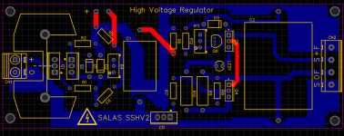
Board made by me from the SSHV2 PDF using easyeda.
Any good idea?
1. connected F+ and F0
2. disconnected zener D1 and D2 across Q1 and Q2
3. 9V input to the CCS with 0,4A wall supply
4. Q1 (DN2540N5) VGS is around 2V
5. Q2 (DN2540N5) VGS is 0V
6. disconnected Q3 (IRF840)
7. tested again voltage across Q1 and Q2 and still same voltages: Q1 VGS around 2V, Q2 VGS=0V
Tested Q1 and Q2 they looks fine
Board made by me from the SSHV2 PDF using easyeda.
Any good idea?

Tested, Q1 sink not touching ground.Maybe Q1's sink touches ground?
Yes, it ranges between 0 and 100Ohm measured across R3R4 works? DMM shows R value going up and down across it? (test when powered off)
The schema I have is a 200R Trimmer in parallel to a 220R. May be I have an old one!Why up to 100 and not to ~200? Is it not a 500R trimmer (parallel to 330R resistor)?
Its OK there are two. One in the original description, one in the PDF. Adjusted for parts availabilty.
Yes, it is insulatedIs Q1's back insulated from the sink anyway? That's the HV carrying MOSFET of the cascode.
- Home
- Amplifiers
- Power Supplies
- Simplistic mosFET HV Shunt Regs