Hello everyone!
I’m not sure if I got it right:
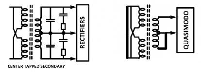
Here’s a toroid with 1 primary and 2 secondaries, to be used in the center-tapped configuration.
With primaries shorted, I connected one secondarie’s wire („AC1“) to Quasimodo‘s comm2-1, and the rest („CT1“, „CT2“, „AC2“) to comm2-2. The result does not look as cleanly damped as with the other secondaries configurations… have I gotten it wrong?
I’m not sure if I got it right:
Here’s a toroid with 1 primary and 2 secondaries, to be used in the center-tapped configuration.
With primaries shorted, I connected one secondarie’s wire („AC1“) to Quasimodo‘s comm2-1, and the rest („CT1“, „CT2“, „AC2“) to comm2-2. The result does not look as cleanly damped as with the other secondaries configurations… have I gotten it wrong?
Attachments

Note.. I think some people get notifications of a new post. I deleted what in hindsight might be a VERY bad idea depending on a few variables... I'll defer to wiser minds...
Thank you, itallinmyhead, but no.
I checked the wires and had them hooked up and running (and checked the wrong position too just to be sure). Also, the centertap-wires were tied together to exclude an error. So I’m sure the wiring’s correct…
I checked the wires and had them hooked up and running (and checked the wrong position too just to be sure). Also, the centertap-wires were tied together to exclude an error. So I’m sure the wiring’s correct…
Looks petty good to me, myleftear. Those little ripples during the 2nd and 3rd division after the 'Ding' look more like setup anomalies than anything to be concerned about. The important thing to remember, IMHO, is the damped reaction from the 'Ding', which in your case looks excellent!
Cheers
Cheers
This is good (comforting) news? 🙂
Looking at it with 24 h distance, it seems obvious: The damping effect changes with the resistor being adjusted. It was just that this one, at the end of the fahnenstange, looks a bit different than all other configuration/the samples in Marks excellent guide.
And as I am one of those blindly going where others have boldly gone before, I quite often believe-but-don't-know something's good/notgood...
So—on to the finicky making of the input-snubber, @pfarrell style!
Last edited:
@Mark Johnson, if I am using a center tapped transformer and I am having trouble finding the capacitors with the Vac rating necessary, could I set it up like this? Just measure from the center tap to the one leg for the one set and the center tap to the other leg for the other set?

Let's pretend that post #2,366 began with "To anyone with Quasimodo experience, I request your help please. ..."
Please feel free to reply and share your knowledge even if the request isn't directly addressed to you.
Please feel free to reply and share your knowledge even if the request isn't directly addressed to you.
bluezee, the first post of this thread has a link to the design and discussion paper "Quasimodo_jig_revA.pdf". Fig 13 of that paper shows your centre-tapped secondary configuration. Mark's suggestion is to just measure one side of the secondary, with the other shorted, and duplicate the identified snubber values.
If you have the time and inclination then you may notice some difference if you deploy the nominal snubber to one side as you test the other side, and then repeat with both sides having their iterated snubber circuit. If there was a difference then that could be due to winding differences and/or measurement differences due to loading of the other secondary half-winding (with the snubber rather than a short circuit). The difference in snubber values may well be within the nominal step size of commercial part values (and the value tolerance of those parts you are using for testing).
If you have the time and inclination then you may notice some difference if you deploy the nominal snubber to one side as you test the other side, and then repeat with both sides having their iterated snubber circuit. If there was a difference then that could be due to winding differences and/or measurement differences due to loading of the other secondary half-winding (with the snubber rather than a short circuit). The difference in snubber values may well be within the nominal step size of commercial part values (and the value tolerance of those parts you are using for testing).
Thank you for your response. Sorry I missed it in the paper. I had looked through a lot of pages on the thread. So it appears my configuration matches his configuration. The "how to" on measuring was helpful as well. TY
Hello Gents,
I bought a quasimodo V4 test jig and I've got a H/K PM665VXi to which I want to add CRC's. I think I fully understand the quasimodo_jig_revA.pdf document describing how it all works but have a few maybe rather obvious questions.
The PM665VXi has 2 seperate transformers. For each channel one transformer. Each transformer (see schematic) has 2 primary windings of which I use only (ie: for AC mains 240, the otherone is for AC mains 220)
Each transformer has 2 center tapped secondary windings producing of which I'm ony using 1 with the highest voltage ( -48/+48 Volt )
The original design also has the 2 cx capacitors with a value of 0.1uF (100nF).
Now here my questions and yes they may sound obvious but I just want to make sure I understand it correctly🙂
1) When I hook up the V4 jig and start testing I need to short both primary windings effectively meaning bringing all 3 wires together?
2) I also need to shortcut the NOT used secondary winding AND as per Quasimodo manual shortcut winding NOT measured / tested?
3) Final question: I find the 100nF in the original design rather big compared to what quasimodo manual is suggesting (cx= 10nF)....is that a problem or I just go with these values and make cs 15x bigger resulting in a value of 1.5uF?
thx in advance
willem
Original transformer scheme of the PM665VXi
willem, the aim is to do the test in the same operating configuration as would be used in practise.
The mains comes in to two primary winding taps, so only those two taps are shorted, as that represents the impedance looking back in to the mains (well sort of in a practical simple sense).
Same situation for the secondary, where the taps that connect to the diode bridge are considered as the only secondary windings being used in the working configuration - so don't connect anything to any other unconnected taps - and test the two taps and centre tap as per the design doc notes (also perhaps review the previous posts relating to bluezee).
See the design notes doc for comments relating to size of Cx etc, and make up your own mind on how practical or otherwise the values are, given the sizes available to you and the parts you have.

Thx Trobbins....what about the cx's value of the original scheme which is 100nF?...The Quasimodo manual actual says to use the original scheme's cx value.
So my question is actually. Shall I use the original 100nF's which are 10 times higher then the usual value of 10nf or could it be that the original designers of the H/K PM665VXi just had it wrong and should I replace them with 10nF? Or doesn't it matter at all......🙂
thx in advance
reg
willem
So my question is actually. Shall I use the original 100nF's which are 10 times higher then the usual value of 10nf or could it be that the original designers of the H/K PM665VXi just had it wrong and should I replace them with 10nF? Or doesn't it matter at all......🙂
thx in advance
reg
willem
Attachments
Perhaps you could test performance with 100nF, and then with 10nF, and rationalize if there is a difference, and what that means for the snubber parts you have, or need, as well as the practical issues with fitting those parts.
This makes me wonder if the values of the other parts will move in a predictable direction? (Will the use of, say, a higher Cx result in a higher Cs/Rs? Or what happens with Rs if I lower/increase Cs?)
Is there a ballpark?
Is there a ballpark?
Well the only ballpark figures I read in Mark Johnson article and manual is that CS should be about 10 to 20 times bigger then CX. I'm gonna measure them both but first need tog et my hands on a scope🙂
w.
w.
I vaguely remember that…
I asked because I am thoroughly insecure about my measurements of a center-tapped configuration—where the pot was at 4.something ohms when I reached a nice curve on the scope...
I asked because I am thoroughly insecure about my measurements of a center-tapped configuration—where the pot was at 4.something ohms when I reached a nice curve on the scope...
Hi wkloppen,
Once you score that 'scope, I would suggest lifting one lead of the original 0,1uF C3 and C5's. Then insert the trimpot in series, making it your Cs. Then fit the more usual 10nF for Cx.
Try not to worry that the original design just stuck a 0,1uF shunt across each transformer secondary. The designer chose a simplified, nominally adequate (arguably) approach that would tolerate a range of rectifier choices and transformer winding vagaries. It's a method the front office often prefers, since it's less likely to go off in the ditch if/when a batch of wildly different power transformers, for example, come in mid-production run.
Best Regards
😀😀....Yeah...could do that. I'm first gonna test on the jig. The tranformers are fully disconnected from the main board. I will remove the old 0,1uF's anyway and replace them with new ones. Lots of room on the board🙂

Antek AS3220 transformer. Primary Shorted, shield floating, and one secondary shorted.
Quasimodo Jog with series 9V battery input. (18V)
Cx = 10nF Cs=150nF
First Wave Form R = infinity

Second Wave Form R = 10 ohm

Third Waveform R =7.5R

Probably splitting hair, but 10 R seems properly dampened and per my eye best fits the example in the documentation. 7.5R appears possibly over dampened. What are your opinions? Also it didn't appear to create a difference how the shield lead was terminated. What is the a preferred way of handling it?
Quasimodo Jog with series 9V battery input. (18V)
Cx = 10nF Cs=150nF
First Wave Form R = infinity
Second Wave Form R = 10 ohm
Third Waveform R =7.5R
Probably splitting hair, but 10 R seems properly dampened and per my eye best fits the example in the documentation. 7.5R appears possibly over dampened. What are your opinions? Also it didn't appear to create a difference how the shield lead was terminated. What is the a preferred way of handling it?
- Home
- Amplifiers
- Power Supplies
- Simple, no-math transformer snubber using Quasimodo test-jig