Mark, I bought a Cheapmoto a while back. Due to a SSD on my computer failing I lost the instructions. Where can I go to download a file?
Ah, me again, with a $0.01-question...
I am totally not sure whether this arrangement of secondaries would qualify as centertapped?
Or, is it rather secondaries in series?
It is somehow obvious, but (obviously) I'm a chicken.
Referring to the (excellent) Quasimodo-documentation, the third, or the last...
according to mZM :

I am totally not sure whether this arrangement of secondaries would qualify as centertapped?
Or, is it rather secondaries in series?
It is somehow obvious, but (obviously) I'm a chicken.
Referring to the (excellent) Quasimodo-documentation, the third, or the last...
according to mZM :
Attachments
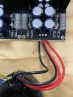
Without seeing the documentation for your transformer, I'd need to assume:
that the black wires are two ends of one secondary;
the red wires are two ends of another secondary;
both secondaries are the same number of turns;
both secondaries are wound in the same direction around the core; and
that you have the phases wired 'correctly'.
I may have forgotten a few things, but in general, if the above is true; you have both wired your independent secondaries in series AND the junction of the black and red wires would effectively be a 'center tap'.
I think I got that correct, but as with all my posts, what I think I know, and what I actually know can be worlds apart. I'd wait for someone else to confirm and/or say where I got this wrong.
I agree with ItsAllInMyHead. Use the last combo of snubbers, one across each winding. To test, you would just test one winding and duplicate the results for the other winding.
Do you have the transformer wiring diagram or documentation? Are the black wires one secondary winding and the red wires the other secondary winding? Do they have dots on them to identify phasing?
You could also ohm out the wires. Assuming the black/red are the secondaries, one pair of black/red should ohm out with low resistance, this is one of the secondaries. The other pair should be ohm out to around the same resistance, this is the other secondary.
If they are independent, then the two blacks will not ohm out, and two reds will not ohm out.
If its really center tapped, then either two blacks or the two reds would be shorted together.
Does that make sense?
Randy
If they are independent, then the two blacks will not ohm out, and two reds will not ohm out.
If its really center tapped, then either two blacks or the two reds would be shorted together.
Does that make sense?
Randy

@myleftear - I answered you with regard to the picture you posted. Once you've determined your transformer's wiring, write again. Also, if you've got a schematic of your PSU, that would be helpful.
In order to use the Quasimodo properly, you'd also need to know how you plan to wire it into your circuit. Mark shows excellent pictures in the guide of different wiring / rectification examples. The same transformer can be wired a number of ways in the circuit.
As a real world example (I can't remember if you've built an Iron-pre, but I think you did), the Iron Pre boards show pads for a center-tap transformer. Note that the boards also have enough pads to easily/intentionally use a dual secondary transformer to produce the equivalent voltage. You can use a dual secondary 18V transformer as the equivalent of a 36V CT.
Your primary wiring is also critical, but I'll assume you've got that correct for your country's mains voltage and your transformer.
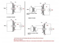
It's also critical to understand the phasing - The attached might help. Credit ZM.
In order to use the Quasimodo properly, you'd also need to know how you plan to wire it into your circuit. Mark shows excellent pictures in the guide of different wiring / rectification examples. The same transformer can be wired a number of ways in the circuit.
As a real world example (I can't remember if you've built an Iron-pre, but I think you did), the Iron Pre boards show pads for a center-tap transformer. Note that the boards also have enough pads to easily/intentionally use a dual secondary transformer to produce the equivalent voltage. You can use a dual secondary 18V transformer as the equivalent of a 36V CT.
Your primary wiring is also critical, but I'll assume you've got that correct for your country's mains voltage and your transformer.
It's also critical to understand the phasing - The attached might help. Credit ZM.
Attachments
So many answers!
I was too focused on my problem to realize I didn’t document the situation appropriately, sorry for that.
The Tx is a toroidy 2 x 18V 50VA, 1 primary, red-red / black-black are the secondaries.
Toroidy, though excellent, doesn‘t document very thoroughly, they don’t even tell us the winding’s orientations (hence the wire’s colours), this I have to find out with quasimodo (I unfortunately didn‘t note it, but there is a clear difference in the results when the wire‘ orientation is swapped when they’re hooked together (parallel or series)…
Aha! 😀
That is precisely my chicken-moment…
The PSU is the DCSTB from Salas (which will feed a DCG3 (scm follows in a minute), and no, I haven’t built an Ironpre, I was/am just drooling about…
edit: here's the PSU's schematic... (which quite clearly indicate what configuration to use, ahem)
I was too focused on my problem to realize I didn’t document the situation appropriately, sorry for that.
The Tx is a toroidy 2 x 18V 50VA, 1 primary, red-red / black-black are the secondaries.
Toroidy, though excellent, doesn‘t document very thoroughly, they don’t even tell us the winding’s orientations (hence the wire’s colours), this I have to find out with quasimodo (I unfortunately didn‘t note it, but there is a clear difference in the results when the wire‘ orientation is swapped when they’re hooked together (parallel or series)…
you have both wired your independent secondaries in series AND the junction of the black and red wires would effectively be a 'center tap'.
Aha! 😀
That is precisely my chicken-moment…
The PSU is the DCSTB from Salas (which will feed a DCG3 (scm follows in a minute), and no, I haven’t built an Ironpre, I was/am just drooling about…
edit: here's the PSU's schematic... (which quite clearly indicate what configuration to use, ahem)
Attachments
Note - I have never built one of those PSUs, but it looks to be set up on 'one' board to do two dual rail PSUs => Dual mono, dual rail. So, it looks like your dual secondary transformer set up as a CT would be the AC supply for one dual rail supply (one half of the board). If you want dual mono, then you'll need one more transformer. Someone more familiar with that supply may be a bigger help on this.
A chunk of the schematic for your PSU is very helpful re: how you'd use it with your Quasimodo to check for the snubber values. However, where on the PCB / within the circuit do you plan to implement the snubber? Do you know if it's useful for this type of PSU? I don't have a point of reference.

So, this would be the implementation for using it with the Quasimodo per the instructions. You measure it not only for how the transformer is configured, but for how you will utilize the transformer in the circuit. In this case, CT.

Once again, I don't know where you'd include the snubber within or in addition to the DCG3 circuit and/or if it's necessary / worthwhile, but that's how I'd measure it were I in your shoes.
Don't forget to look for phase dots and/or be sure to check your phasing manually (ACVM) before hooking it to the Quasimodo. Yes, you should certainly seen your measurements behave differently based on how you wired your secondaries (orientation and overall in series or parallel). Be sure to review the ZM attachment and measure. 🙂
Hope that helps. Once again... grain of salt with my answers. I've never used that PSU, and I could be very, very wrong. I like to work through this stuff to learn alongside. I think I've got it correct or I wouldn't have posted, but my answer should not be the definitive answer.

A chunk of the schematic for your PSU is very helpful re: how you'd use it with your Quasimodo to check for the snubber values. However, where on the PCB / within the circuit do you plan to implement the snubber? Do you know if it's useful for this type of PSU? I don't have a point of reference.
So, this would be the implementation for using it with the Quasimodo per the instructions. You measure it not only for how the transformer is configured, but for how you will utilize the transformer in the circuit. In this case, CT.
Once again, I don't know where you'd include the snubber within or in addition to the DCG3 circuit and/or if it's necessary / worthwhile, but that's how I'd measure it were I in your shoes.
Don't forget to look for phase dots and/or be sure to check your phasing manually (ACVM) before hooking it to the Quasimodo. Yes, you should certainly seen your measurements behave differently based on how you wired your secondaries (orientation and overall in series or parallel). Be sure to review the ZM attachment and measure. 🙂
Hope that helps. Once again... grain of salt with my answers. I've never used that PSU, and I could be very, very wrong. I like to work through this stuff to learn alongside. I think I've got it correct or I wouldn't have posted, but my answer should not be the definitive answer.
Last edited:
Patrick!
Thanks again for assisting me. Here's what will be in the box—as you concluded, two dual rails aka a dual mono beast.
The placement of the anti-ring-network would obviously be at the PSU's entry. Will ask Salas before, just to be sure it makes sense at all (AFAIK, tea-bag/Salas did recommend the use of Quasimodo)
And, last not least, thanks to Rick and Randy for your thoughts too! Much appreciated!
Attachments

Hi All,
with regard to finding the transformer phasing for the correct orientation of the leads for the quasimodo, what would be the best method for transformers with several secondaries - or do you just go with one? I have a transformer with 3 secondaries, and I think a center tap, but no documentation....Following on from that, how would that translate ( or would it need to ) to the in situ connections onto the Bridge rectifier once the C/RC snubber had been attached?
Many thanks in advance
Joe
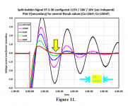
One possibility among many, is discussed in this thread
A little tester to determine transformer PhaseDots with no scope or signal generator
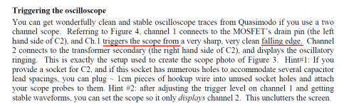
And if it turns out that you do have an oscilloscope, you can use the setup shown in Figure 1 of the first message in that thread. Without building a PhaseDots tester.
A little tester to determine transformer PhaseDots with no scope or signal generator
And if it turns out that you do have an oscilloscope, you can use the setup shown in Figure 1 of the first message in that thread. Without building a PhaseDots tester.
Hi All,
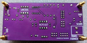
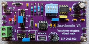
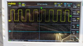
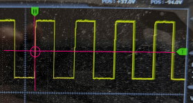
I have a problem with my Quasimodo.
Shortly, All my transformer winding are shorted except the one I want to mesure,
on channel 1 I have the square wave but on channel 2 nothing at all, no oscillation (he's dead Jim).
I figure I have made something wrong when I soldered the parts, so I constructed another one, same result.
Tested with an other transformer, same result.
Tried an other scope, again same result
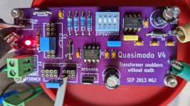
I send pictures of the beast, sometime you could see something that I am not able to see myself.
Thanks
I have a problem with my Quasimodo.
Shortly, All my transformer winding are shorted except the one I want to mesure,
on channel 1 I have the square wave but on channel 2 nothing at all, no oscillation (he's dead Jim).
I figure I have made something wrong when I soldered the parts, so I constructed another one, same result.
Tested with an other transformer, same result.
Tried an other scope, again same result
I send pictures of the beast, sometime you could see something that I am not able to see myself.
Thanks
Attachments
Hello Mr. Johnson,
Thanks for your help, it is working well now. 👍 It is a wonderful tool. 🙂 I will take the opportunity to ask you, what is the minimum power the resistor need to be for the snubber.
It is for a 1kva transformer, if it is important.
Thanks for your help, it is working well now. 👍 It is a wonderful tool. 🙂 I will take the opportunity to ask you, what is the minimum power the resistor need to be for the snubber.
It is for a 1kva transformer, if it is important.
Hi Mark,One possibility among many, is discussed in this thread
A little tester to determine transformer PhaseDots with no scope or signal generator
And if it turns out that you do have an oscilloscope, you can use the setup shown in Figure 1 of the first message in that thread. Without building a PhaseDots tester.
Many thanks. Just one more question is the polarity hook up completely arbitrary for the primary? As my transformer has no dots at all, I guess join all the primary’s in series ( multiple voltages ) and just pick a side to be +? I have both function generator and oscilloscope.
Kind Regards
Joe
When assigning phase dots, the FIRST winding is completely arbitrary. Flip a coin and mark one the ends of the first winding with a dot.
ALL OTHER windings are compared to the first winding. For winding #2 put a dot on the end that is in phase with the dotted end of the first winding.
For winding #3 put a dot on the end that is in phase with the dotted end of the first winding.
etc.
This is not a Quasimodo problem, it is an unknown transformer problem. Consider searching for a thread about that, and posting there. Or if none exists, create a new thread.
- Home
- Amplifiers
- Power Supplies
- Simple, no-math transformer snubber using Quasimodo test-jig