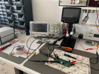
Another Quasimodo lives!
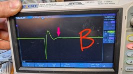
I built it up last night, but only getting to use it tonight. After figuring out how t trigger the scope properly etc, I think I have stable waveforms. I connected up a random 12v transformer and was able to adjust the pot to get pretty close to the pictures in the manual that @Mark Johnson kindly provided - not quite as clean, but not bad. I also tried a much heftier 40V transformer and that was cleaner looking. Finally I pulled out my Aleph J, big 20V transformer and hooked it up. The results are below.
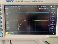
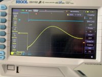
A: This first one is essentially undamped - I think the pot was up around 500R or so.

B: If I'm right, this one is I think the goldilocks spot - just damped, maybe a tad underdamped:

C: And this one I think is over damped.

I hope I have that right - If I do then I'm well on my way.
On all 3 of the transformers I measured with standard capacitors as per the manual, the resistor reading is quite low - from 15R to 30R. Is this normal? Should I change the capacitor values to achieve a higher resistance?
Fran
I built it up last night, but only getting to use it tonight. After figuring out how t trigger the scope properly etc, I think I have stable waveforms. I connected up a random 12v transformer and was able to adjust the pot to get pretty close to the pictures in the manual that @Mark Johnson kindly provided - not quite as clean, but not bad. I also tried a much heftier 40V transformer and that was cleaner looking. Finally I pulled out my Aleph J, big 20V transformer and hooked it up. The results are below.
A: This first one is essentially undamped - I think the pot was up around 500R or so.
B: If I'm right, this one is I think the goldilocks spot - just damped, maybe a tad underdamped:
C: And this one I think is over damped.
I hope I have that right - If I do then I'm well on my way.
On all 3 of the transformers I measured with standard capacitors as per the manual, the resistor reading is quite low - from 15R to 30R. Is this normal? Should I change the capacitor values to achieve a higher resistance?
Fran

Great stuff, thanks @Mark Johnson
I think I read somewhere that slightly under-damped is better than overdamped - am I correct in this? I couldn't find the place I saw it afterwards.
I think I read somewhere that slightly under-damped is better than overdamped - am I correct in this? I couldn't find the place I saw it afterwards.
Hi all...
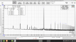
Lately i build a FFT measurement setup for testing my amplifier's. Link!
But this lead me to some issue's i see in some of my amps.
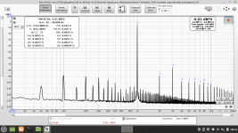
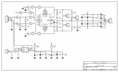
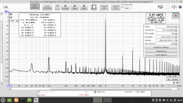
Attached picture here is a somewhat cheap LM4780 Cloneamp. (Schematic + FFT shoot)
(Feed with Victors 1KHz osc. at 1.055v ---> CloneAmp. ---> 8ohm-load ---> Soundcard)
I belive it's mostly 100Hz rectifier "noise" bleeding through the PSU (50Hz mains here in Denmark)
I'am in doubt if the Quasimodo snubber will help curing this? Or if the ringing it would cure are somewhat another issue
- I see it could be obvious but i can't really find anywhere showing this.
(For sure i'am up for building it, could be i cannot resist nomatter what)
Jesper.
Lately i build a FFT measurement setup for testing my amplifier's. Link!
But this lead me to some issue's i see in some of my amps.
Attached picture here is a somewhat cheap LM4780 Cloneamp. (Schematic + FFT shoot)
(Feed with Victors 1KHz osc. at 1.055v ---> CloneAmp. ---> 8ohm-load ---> Soundcard)
I belive it's mostly 100Hz rectifier "noise" bleeding through the PSU (50Hz mains here in Denmark)
I'am in doubt if the Quasimodo snubber will help curing this? Or if the ringing it would cure are somewhat another issue
- I see it could be obvious but i can't really find anywhere showing this.
(For sure i'am up for building it, could be i cannot resist nomatter what)
Jesper.
Attachments
Thanks Mark.Have a look at Figure 10 on page 8 of the Quasimodo design note.
I allready read a lot, but still i cannot see nor read anywhere if it will eventually cure such spikes (100hz + harmonics)
Please bare with me I am new into this, and believe me I try to read / figure it out
🙂 Jesper.
I did some more intensive reading now.
Looking closely at the note - i clearly see the point in doing this that transformer won't "ring/vibrate" any longer ::

But still cannot find any info why this can cure 100/120Hz noise. (Other than affecting diode turn-off somehow ???)
I found somewhere where it was discussed, but didn't gave me any clear answer also 🙂
Jesper.
Looking closely at the note - i clearly see the point in doing this that transformer won't "ring/vibrate" any longer ::
But still cannot find any info why this can cure 100/120Hz noise. (Other than affecting diode turn-off somehow ???)
I found somewhere where it was discussed, but didn't gave me any clear answer also 🙂
Jesper.
At what frequency are the diodes switched on and off? I think that is what Mark is getting at. The ringing at 100/120Hz would cause harmonics.
HI...
I think the ringing on the Figure 10 are somewhere around 10KHz, eventhrough i'am not sure i did the math correctly.
The diodes are switching off somewhere between 100ns and 500ns depending on type.
This is somehow bleeding into the amplifier, and can be measured with RTA/FFT around 100Hz/120Hz depending on the mains freq.
That's only what i think, still i cannot seem to find the info about it clear (Also i'am non native English, which makes it harder to understand)
But i think i'am going to build it anyway, would just be very nice to have some kind of explanation that is 🙂
Jesper.
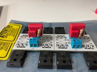
Point to point snubber board for hafler 9500 high current secondary trafo Cx .15uf, CS .002, Rs 25


Hi all.
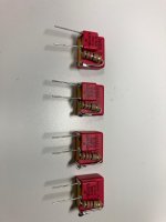
So i had my board's produced, and today i assembled one of them.
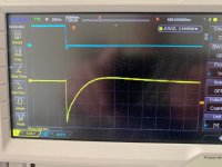
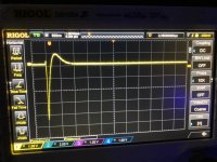
First test is an Talema 2x6v (parallel) with primary tied together as pr. the Quasimodo .pdf (Talema 91227-P2S2)
(The trace are flat when potmeter is at ~26ohm, so i tried an 22ohm resistor, and look's like its good)
I have attached shoots here, with text to see what i did.
But eventhrough i see that the scopetraces don't care when switching frequenzy, i fell that it was better to start with 100Hz here in EU? - Can somone explain why it obviously don't matter.
I have read a lot, especially around this post here Link! - Ahh... just need some little explanation 🙂
Jesper.
So i had my board's produced, and today i assembled one of them.
First test is an Talema 2x6v (parallel) with primary tied together as pr. the Quasimodo .pdf (Talema 91227-P2S2)
(The trace are flat when potmeter is at ~26ohm, so i tried an 22ohm resistor, and look's like its good)
I have attached shoots here, with text to see what i did.
But eventhrough i see that the scopetraces don't care when switching frequenzy, i fell that it was better to start with 100Hz here in EU? - Can somone explain why it obviously don't matter.
I have read a lot, especially around this post here Link! - Ahh... just need some little explanation 🙂
Jesper.
Attachments

Take a look at the V.4 Quasimodo schematic -- you'll see that its DIP Switch lets you select four different stimulus frequencies. First, measure these four frequencies. (Measure the period of the waveform in oscilloscope grids, then frequency = (1/period)).
Then, using the same transformer in each experiment, operate Quasimodo four times: once with each of the four different stimulus frequencies. Find the optimum four values of Rsnub, at these four frequency settings.
Do the answers make you say "Eureka!" ??
_
Then, using the same transformer in each experiment, operate Quasimodo four times: once with each of the four different stimulus frequencies. Find the optimum four values of Rsnub, at these four frequency settings.
Do the answers make you say "Eureka!" ??
_
Attachments

Hi Mark... Thank's for the reply 🙂Take a look at the V.4 Quasimodo schematic -- you'll see that its DIP Switch lets you select four different stimulus frequencies. First, measure these four frequencies. (Measure the period of the waveform in oscilloscope grids, then frequency = (1/period)).
Then, using the same transformer in each experiment, operate Quasimodo four times: once with each of the four different stimulus frequencies. Find the optimum four values of Rsnub, at these four frequency settings.
Do the answers make you say "Eureka!" ??
_
I allready did change the dipswitch (see picture names & on the scope pictures)
I also see, that the trace do not change, when changing freq. that is!
But i need some explanation why it is not better to start out with 100Hz here in EU, instead of 120Hz, when we know, that the diodes are triggered at that freq. here?
Maybe i need a kick to understand this?
Jesper.
Jasper,
The frequency of the square wave is irrelevant for the ringing itself and Chosen to support scope triggering for a stable picture. The ringing itself is started solely by the square waves‘ EDGE!
When you see the dampened oscillation starting at the negative going edge, you just do the Pot tuning to achieve the minimal ringing as described.
Hope this helps!
Winfried
I allready posted this in another thread, but for the sake of it i will post it here to. Link!
I have this CloneAmp. which i do a lot of experiementation on 🙂 and adding snubber's are doing a great job cleaning up some of the noise from this little amp.
Pictures speak for themself.
Jesper.
I have this CloneAmp. which i do a lot of experiementation on 🙂 and adding snubber's are doing a great job cleaning up some of the noise from this little amp.
Pictures speak for themself.
Jesper.
Attachments
I fail to see ill effect of overdamping.Great stuff, thanks @Mark Johnson
I think I read somewhere that slightly under-damped is better than overdamped - am I correct in this? I couldn't find the place I saw it afterwards.
I just built some snubbers for my Toroidy 300VA (dual mono F6). The Quasimodo gave the same measurement on my scope (12R resistor) as mentioned in the results thread.
Now I need to figure out if I can stick them in Tea-bag's boards ...
Now I need to figure out if I can stick them in Tea-bag's boards ...
Attachments
Last edited:
- Home
- Amplifiers
- Power Supplies
- Simple, no-math transformer snubber using Quasimodo test-jig