The other power transformer issue is the 50Hz/60Hz thing. Transformers are usually specified as dual standard, but it only really works one way.
A transformer designed for 50Hz operation will always work at 60Hz, because the core induction is lower at 60Hz than at 50Hz (by the ratio 5/6, so about 17% lower).
But the rub is that if a transformer is designed for 60Hz, and then it is imported into a 50Hz country, the core induction exceeds the design value by 6/5 - or 20%. That can (and usually does) result in core buzz as the core moves towards saturation. I've had Krell and Audio Research power amps that did precisely that - particularly the Audio Research stuff.
the 400 Hz system has 6.6x more diode shutoffs -- bell ringing events -- per second, and the snubbers have less available time to quench them.
I can't see how any practical snubbered winding meant for 400Hz would have an oscillatory response that extended from the time of 'diode off' through to the next 'diode on' time for a typical capacitor input filtered power supply. For a 400Hz supply, a half cycle is 1.2ms, and if the diode was on for what would be a long 50% of that duration, then the diode off duration is circa 600us. If a few snubbered oscillations took 300us then the resonant frequency would be down below 10kHz.
A snubber for a 400Hz system would nominally use a smaller shunt capacitor than a 50/60Hz system, just to constrain the level of fundamental mains current through it
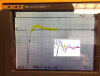
My first attempt at using the Quasimodo appeared to go flawlessly but still left me a little puzzled.
Here's R infinity which looks exactly the same as other posts.

Here's R tuned to remove all the ringing. Very nice flat line with no hump.

And here's a pic of R tuned too far and the ringing returns.

The thing that puzzles me is that my ideal R is 4.7 ohms which is quite a bit lower than other posts I've read.
Regards,
Dan 😕
Here's R infinity which looks exactly the same as other posts.
Here's R tuned to remove all the ringing. Very nice flat line with no hump.
And here's a pic of R tuned too far and the ringing returns.
The thing that puzzles me is that my ideal R is 4.7 ohms which is quite a bit lower than other posts I've read.
Regards,
Dan 😕
Think looks you over damp see first post at attached guides and pictures.

Opooopppsss I might have to RTFM! 🙄
Regards,
Dan
too big a resistor is equivalent to having no snubber and you see long lasting ringing.
Too small a resistor is equivalent to just hanging a capacitor across the transformer secondary and again you see long lasting ring.
Your first and second pics confirm this.
With a useful range of resistance you see the damped ringing, or the jump plus one half wave.
I have not yet seen the jump without any half wave. That would be the equivalent to a Bessel Filter step. Would that be a good target to find and adopt?
Simulation's an easy way to gather insight, and it lets you change things easily to see whether X has an effect upon Y, and in which direction, and how much. For simulation purposes I suggest setting Cx = 10 nanofarads and Cs = 2.2 microfarads (!!). This is a bigger value of Cs than you'd probably spend the money to buy in real life, but in simulation it's completely free. A really large Cs will let you roam around and explore a giant range of damping factors and or quality factors "Q". Even the ones with surnames.
I've copied the LTSPICE simulation file from Cheapomodo post#1 and attached it here.
_
Professional EEs, on the other hand, don't need any advice from me; they can design to whatever value of zeta they please. Since the transformer secondary circuit is a second order system, these folks can make a Q-to-zeta calculation and wind up with "Butterworth alignment" snubbers, "Bessel alignment" snubbers, and more. Impressive and fancy!
I've copied the LTSPICE simulation file from Cheapomodo post#1 and attached it here.
_
Attachments
Great start Dan! You want the second lumpity bumpity in the waveform to just barely flatline, as shown by the yellow arrowhead in the QM design note figures. Member BYRTT has kindly copied it into posts 904 and 905 above. Your goal is to juuuuust barely ooch your way little by little, until that trough flatlines. Then stop!
Mark Johnson's note transformer secondary circuit is a 2nd order system and for me CRC snupper looks like be 1st order then think AndrewT thaughts about Bessel filter won't help because to my knowledge in 1st order family a butterworth or Bessel is same slope but not when in 2nd order category. Therefor think if ringing minimal is a goal then snupper circuit need be a 2nd order and same filter family as transformer be it butterworth or bessel or whatever.
Last edited:
BYRTT, the transformer secondary and the snubber are connected, and together they form an RLC circuit. Thanks to the two energy storage elements, the RLC circuit is second order. You can see this by plotting the magnitude of impedance vs. frequency. The slope of this plot is 40 dB/decade, which is twice as steep as a first order system slope (20 dB/decade).
You can indeed select resistor values for this RLC circuit and get a Butterworth transfer function, or a Bessel transfer function, or an infinite number of others. However these confer no special benefit and I see no compelling reason to do so, except perhaps marketing and advertising. And the person who writes these advertisements isn't going to worry too much about the technical distinction between "Bessel snubber" and "Bessel transfer function of the transformer+snubber RLC circuit". He's just going to use whichever phrase sounds the most impressive and authoritative.
You can indeed select resistor values for this RLC circuit and get a Butterworth transfer function, or a Bessel transfer function, or an infinite number of others. However these confer no special benefit and I see no compelling reason to do so, except perhaps marketing and advertising. And the person who writes these advertisements isn't going to worry too much about the technical distinction between "Bessel snubber" and "Bessel transfer function of the transformer+snubber RLC circuit". He's just going to use whichever phrase sounds the most impressive and authoritative.
Last edited:

Here's my last foray into Quasimodo land for a little bit. Looks like Rs for my 600VA Antek is going to be 17.5 ohms.
Regards,
Dan

Regards,
Dan
snubbers on secondary and on diodes
I'm building a PSU for a large Class A amp on a nice PCB I got a couple of years ago. There is provisions for Cx and I can of course also fit in Cs and Rs in some way. Quasimodo and toroids on their way.
My question relates to the fact that the PCB also have provisions for snubbers for each of the diodes. The question is if I'm better of snubbering both the secondary and the diodes, or only the secondary, or only the diodes😕
I will be using Scottky diodes for rectification and do not plan to use any inductor/resistor filtering in the reservoir bank.
Do as you like. Personally, I like to connect one snubber per secondary winding, as close to the transformer as possible. Part of the reason I prefer this choice is, it means the test arrangement with Quasimodo (on the lab bench) is very, very close to the actual arrangement inside the final equipment. If the ringing is damped on the bench, it'll also be damped in the end-product. Naturally, other engineers have different opinions. Use your intuition and engineering good judgment to make the best decision that gives you the most confidence. Or else, attempt to make the decision that's the least bad, in the worst case. Maybe you'll do some pencil and paper calculations, maybe you'll run some simulations.
Mark
Your suggestion on snubbing a center tapped transformer
Was to short one secondary and snub the other
And then generally assume that the sane snubber should work for the other secondary
Do you need to go back and forth to confirm
When you have both snobbers installed how do you confirm
Can you ring the entire secondary and see if it's snubbed
Properly
Just looking for a logical way to proceed here
I recommend you use the same thought process, the same procedure, and the same analysis you would use for two completely independent secondaries. Just pretend that you were the one who decided to short winding A's no_dot terminal to winding B's yes_dot terminal, and not some guy at the transformer factory. Then apply Quasimodo to windings A and B exactly as you would do on a transformer with completely independent secondaries.
You can double check the dots using a signal generator and oscilloscope, as shown in Figure 1 of post #1 of (this thread). There are other ways to do it too; messages in that thread discuss a couple alternatives.
_
You can double check the dots using a signal generator and oscilloscope, as shown in Figure 1 of post #1 of (this thread). There are other ways to do it too; messages in that thread discuss a couple alternatives.
_
Attachments
What's weird here on this split bobbin transformer is the resistance and inductance are the same for each secondary
But when I short the primary the inductanceschange significantly
This is not typical of the split bobbins i have on hand
I guess it suggests that I have to use different snubber values for each secondary
But when I short the primary the inductanceschange significantly
This is not typical of the split bobbins i have on hand
I guess it suggests that I have to use different snubber values for each secondary
What's weird here on this split bobbin transformer is the resistance and inductance are the same for each secondary
But when I short the primary the inductanceschange significantly
This is not typical of the split bobbins i have on hand
I guess it suggests that I have to use different snubber values for each secondary
Surely that is to be expected? With the primary open you are measuring the secondary inductance, which will be large. But with the primary shorted you are measuring the leakage inductance, typically ~1mH for a split bobbin, but can be much higher.
Yup - just tested a random ~150VA split bobbin on my bench. Secondary inductance 40mH with primary open. With primary shorted leakage inductance is 1.5mH
Yup - just tested a random ~150VA split bobbin on my bench. Secondary inductance 40mH with primary open. With primary shorted leakage inductance is 1.5mH
Hmmm, what happens in the vast gulf between "primary open" and "primary shorted"? How can we interpolate and study "primary part-way shorted" ?
One way to do it, is to realize that "primary shorted" means "primary connected to a zero picohenry inductor". Since a zero-valued inductor is a short circuit, this seems valid. Similarly, "primary open" means "primary connected to an infinity henry inductor". Since an infinity henry inductor has infinite AC impedance, this seems valid.
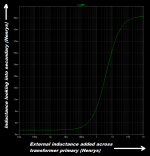
So I did that, in simulation. I made a 230VAC primary, 23VAC secondary transformer whose secondary magnetizing inductance was 40 millihenrys and whose primary magnetizing inductance was 4.0 henrys. It turned out that the mutual inductive coupling coefficient which gave a secondary leakage inductance (primary SHORTED) of ~ 1.5 millihenrys, was K=0.9812. So I used that K value.
Then I disconnected the short across the primary and connected an external inductor to the primary, whose value is changeable in simulation. I verified that when Lexternal=0, the (leakage) inductance looking into the secondary was ~ 1.5 mH in simulation. I also verified that when Lexternal=Infinity, the inductance looking into the secondary was ~ 40 mH in simulation.
Then I simulated 25 values of external inductance, between zero and infinity. Results plotted below.
At the far left side of the plot, external L is very small. Almost zero. And the inductance looking into the secondary is ~ 1.5 mH. At the far right side of the plot, external L is very large. Almost infinity. And the inductance looking into the secondary is ~ 40 mH. In between, the inductance follows a smoothly rising curve.
It was a pleasant way to spend an hour!
_
Attachments
- Home
- Amplifiers
- Power Supplies
- Simple, no-math transformer snubber using Quasimodo test-jig