If you will provide three or four before-and-after scope photos, showing a transformer + snubber whose ringing is completely removed in Quasimodo testing on the bench, but when that transformer and that snubber are installed in the final equipment and tested "in situ", ringing is present -- I will put those photos into the Quasimodo design note with full attribution.Mark may wish to ... describe where the setup for the test-jig with a test transformer may differ from an actual circuit's operational conditions.
However I am willing to wager GBP 100 that no such photos will be presented any time between now and 01 November 2017 (18 months).
Why do you need photos to suggest an awareness that real situations are not always covered exactly by a single test scheme?
If you will provide three or four before-and-after scope photos, showing a transformer + snubber whose ringing is completely removed in Quasimodo testing on the bench, but when that transformer and that snubber are installed in the final equipment and tested "in situ", ringing is present -- I will put those photos into the Quasimodo design note with full attribution.
However I am willing to wager GBP 100 that no such photos will be presented any time between now and 01 November 2017 (18 months).
I suspect I can find a power line that bad. What normally happens is that the electrical code allows for a 5% voltage drop power line transformer to main panel and another 5% panel to outlet. Now the distribution network is at high voltage and has many taps on it. So the impedance of the power line is reduced by the impedance of the loads and then finally by the transformers step down action.
Given the distribution allows 10% losses before the transformer, 5% loss at the panel run rated for 100 amps at 120 volts and a final 5% to a 15 amp outlet that would give a line impedance of .536 ohms worst case.
Now for a reasonable power transformer of say 500 watts that would be around a two to one step down transformer or an added line resistance to the secondary of around .135 ohms. I think if my math is right that could cause a 1.7% shift in the resonant frequency. (You are using 1% tolerance parts for the snubber!!)
Now if I can find a really worst case power line and a transformer with a very sharp resonance I think I just might be able to measure the damping change.
Is that going to happen in practice? Probably not with any well made transformer.
BTY measured AC line impedance is almost always under .05 ohms. But with the higher line voltages in G.B. it might go a bit above that.
The impedance of note is at the frequency related to the diode induced effect, not at mains frequency (which relates to the regulation derived values you have deduced).
The purpose of Quasimodo is to provide wide-band excitation to a circuit comprising the leakage inductance of the transformer, whatever capacitance is present (parasitic and/or Cx-added), and some small resistance of the secondary winding being tested. The excitation energy comes from the steep falling edge in the secondary current when the output MOSFET starts conducting in each pulse.
Depending upon the configuration, an oscillatory circuit is characterised by one or more so-called natural frequencies, sometimes referred to as modes, and will oscillate at these frequencies if there is enough excitation energy. We then speak of resonance(s).
Assuming that there is only a single natural frequency, we see a sinusoidal pattern on the oscilloscope, generally decaying with time due to the natural damping in the circuit, provided by e.g. winding resistance.
So the key facts are that there are a circuit that can oscillate if excited and enough excitation energy at the circuit's natural frequency.
Going over to the same transformer in a PSU with rectifiers, whenever a rectifier diode stops conducting there will be a more or less steep falling edge in the secondary voltage, which in turn may provide excitation energy for the resonance to happen. Without a snubber, this oscillation is clearly visible on the scope in most cases; and by connecting an appropriate Rs-Cs combination parallel to the secondary winding the oscillation can be quenched. Note that the PSU must be loaded for this test to work, but not necessarily with the full load. Several screenshots obtained in such testing can be seen in Post #735.
So from the standpoint of physics, both methods satisfy the purpose of the procedure, i.e. determining the snubber configuration that prevents the parasitic oscillations from taking place. However, due to the different testing conditions, they may not produce the same Rs value.
I routinely use Quasimodo to determine an optimal snubber for every incoming transformer, but I also check for ringing in the PSU built with this transformer. In my experience, oscillations in situ can usually be quenched with a higher Rs value than determined with Quasimodo, which results in less dissipation.
Regards,
Braca
The impedance of note is at the frequency related to the diode induced effect, not at mains frequency (which relates to the regulation derived values you have deduced).
??
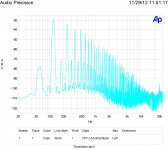
Attached is an FFT of the spectrum of a rectified and filtered signal. The main energy is at twice the line frequency.
The ringing frequency is not related to this. It is determined by the winding inductance and capacitance.
Some of the ringing is damped by any actual circuit load.
Testing with the windings not under test shorted will result in a worst case value.
Attachments
Sounds like whoever accepts my GBP 100 wager, may have a good probability of winning!* All someone has to do is find one transformer and one AC mains outlet and one piece of equipment and one lucky moment when the voltage sag is worst (right when Barcelona Football Club TV programme comes on??). Then snap a picture of visible transformer oscillatory ringing "in situ" using the same transformer and snubber that gave perfect damping on the bench using Quasimodo. Snap a picture of the bench/Quasimodo waveform too. Finally snap a picture of the equipment itself showing the transformer and snubber inside.
I have a feeling that SPICE circuit simulations may accelerate your progress towards winning the wager. First try out all of your hypotheses about "what might make ringing appear in real equipment with real mains and real multiple secondaries, that doesn't appear in Quasimodo testing?" Put each one into SPICE and see how big or how small the effect seems to be. Then try out all of the other hypotheses you may have seen, here and elsewhere. Put each one into SPICE and see how big or how small the effect seems to be.
Then once you know which hypotheses seem to have the biggest effects (at least in simulation) try them first! Concentrate your lab testing efforts upon the ideas which appear to have the greatest likelihood of winning the bet.
If you are so inclined, share your SPICE simulation results with others. Maybe somebody else will offer an analysis of your data, that you never thought of, helping propel you to victory much sooner. Or maybe that somebody else is your competitor, "the enemy", with whom you ought not share anything?
*Lovely word, "may". The sun may explode next month. Undeniably true.
Last edited:
Sounds like whoever accepts my GBP 100 wager, may have a good probability of winning!* All someone has to do is find one transformer and one AC mains outlet and one piece of equipment and one lucky moment when the voltage sag is worst (right when Barcelona Football Club TV programme comes on??). Then snap a picture of visible transformer oscillatory ringing "in situ" using the same transformer and snubber that gave perfect damping on the bench using Quasimodo. Snap a picture of the bench/Quasimodo waveform too. Finally snap a picture of the equipment itself showing the transformer and snubber inside.
I have a feeling that SPICE circuit simulations may accelerate your progress towards winning the wager. First try out all of your hypotheses about "what might make ringing appear in real equipment with real mains and real multiple secondaries, that doesn't appear in Quasimodo testing?" Put each one into SPICE and see how big or how small the effect seems to be. Then try out all of the other hypotheses you may have seen, here and elsewhere. Put each one into SPICE and see how big or how small the effect seems to be.
Then once you know which hypotheses seem to have the biggest effects (at least in simulation) try them first! Concentrate your lab testing efforts upon the ideas which appear to have the greatest likelihood of winning the bet.
If you are so inclined, share your SPICE simulation results with others. Maybe somebody else will offer an analysis of your data, that you never thought of, helping propel you to victory much sooner. Or maybe that somebody else is your competitor, "the enemy", with whom you ought not share anything?
*Lovely word, "may". The sun may explode next month. Undeniably true.
Is it cheating too much if I wind my own resonant power transformer? I think I could do something along the lines of a constant voltage transformer where it normally runs in saturation that would then show some shifts in values when run at lower voltages. (Thinking along the lines of a saturable reactor. https://en.wikipedia.org/wiki/Saturable_reactor )
The comes the issue of visible, I can look clearly below 1 nV/RtHz with some of my test gear.
🙂
Last edited:
Mark is effectively showing that any snubber that gives a reasonably good effort in a quasimodo type test setup will perform in situ such that no oscillatory behaviour would be measurable. There is a fair tolerance to the RC tuning in practice.
That is supported by no one presenting any oscilloscope plots to the negative.
That is supported by no one presenting any oscilloscope plots to the negative.
Dear simon7000- I think the idea is to show that at least one piece of reasonably decent audio equipment does in fact (i) have transformer ringing "in situ," and at the same time, (ii) has no ringing at all in the lab using Quasimodo. So I think winding your own intentionally-bad transformer is probably out of bounds, because no one in their right mind would buy it and put it into a piece of audio gear.
On the other hand if you can find a piece of commercially available audio equipment which does contain a constant voltage transformer or a saturable reactor, which the designer selected & installed deliberately and intentionally, I think that transformer and that audio gear is completely acceptable. And you will be GBP 100 richer after accepting and winning the wager.
On the other hand if you can find a piece of commercially available audio equipment which does contain a constant voltage transformer or a saturable reactor, which the designer selected & installed deliberately and intentionally, I think that transformer and that audio gear is completely acceptable. And you will be GBP 100 richer after accepting and winning the wager.
On the other hand, "stacking the deck" by deliberately choosing to operate the equipment in a worst case environment, seems perfectly OK to me. You cannot build foolproof circuits because fools are so ingenious.
So for example if your hypothesis is that long runs of AC mains cable can make this worse, then by all means perform your tests at a remote farmhouse, which is three miles from the pole-mounted transformer and 100 miles from the generator.
If your hypothesis is that mains impedance at 100 kHz can encourage ringing which Quasimodo doesn't know about, feel free to plug your gear into commercial "line conditioners" and/or surge protectors and/or Powerbloc Regenerators, and/or RFI-EMI filters, which change the HF mains impedance as seen by the audio equipment. Plug four or five of them in cascade (series) if you like.
Shoot, if you dare, go ahead and plug your audio equipment into a 12VDC --> 115VAC (230VAC) "inverter" that lets you run AC appliances from an automobile battery + alternator (for short periods). It's mildly insane but possibly illuminating. Surely this maximizes the difference between Quasimodo (primary shorted) testing, and "in situ" operation with the world's worst AC mains sinewave. But if the inverter completely destroys your audio gear, it's your fault and not mine.
Maybe you imagine that older equipment with two-pin mains power cable (no protective ground wire) is more susceptible. Go ahead and try that. Maybe you think that equipment with a circuit breaker instead of a fuse, is more susceptible. Go right ahead. Maybe you think a slow-blow / time delay fuse is more susceptible, due to the added inductance of the coiled wire inside the fuse capsule. Help yourself.
The topic was discussed in post #306. It relates to measurements of the source impedance of various AC supply outlets that connect to electrical equipment. I recall an IEEE paper on how they came to standardise on a LISN for the purposes of applying EMC standards, but can't locate that insightful reference. A LISN is just a standardised representation of what an amplifiers transformer would see if it looked back in to a generic mains supply. The point being that the AC supply will have some low level of impedance at the frequency of interest (which could be many tens for kHz, depending on the power supply under test).
If oscillatory energy is flowing around in a transformer winding, then it has a number of paths it can couple to (such as the primary winding). The quasimode type test provides a step change to the transformer on one winding section. Hegeman just applied standard leakage inductance test setup, which Mark has followed, whereby all other windings are short circuited. That will give a particular resonant response. If windings aren't short circuited, or are interconnected by ground straps, then the resonant response is somewhat changed, and may change the optimum damped response RC values of a snubber being set up in the test jig.
Placing a snubber with RC values optimised for one or other test setup conditions would similarly work in situ, in that any oscillatory current caused by the in-situ environment would flow in the snubber compared to not having a snubber present.
The resonant frequency of an RLC circuit does not depend on R at all. R only effects the damping, and does not change the resonant frequency.
How much does it change the damping? Even ignoring core losses and just looking at the resistive losses, the mains impedance is still insignificant. Checking a handful of transformers of differing constructions the primary resistance was in the range 10 to 40 ohms. Even if the mains resistance was an outrageously high 1 ohm its effect would be entirely insignificant in the context of using Quasimodo.
How much does it change the damping? Even ignoring core losses and just looking at the resistive losses, the mains impedance is still insignificant. Checking a handful of transformers of differing constructions the primary resistance was in the range 10 to 40 ohms. Even if the mains resistance was an outrageously high 1 ohm its effect would be entirely insignificant in the context of using Quasimodo.
Hi sawyers,
Post #842 talks about a 2 x 24VAC toroidal transformer rated 600 VA. Member dantwomey just built his Quasimodo jig and is awaiting delivery of this transformer so he can optimize snubbers for it.
The manufacturer's "data sheet" such as it is (link), doesn't state primary winding resistance directly. But perhaps it is possible to make a couple of reasonable assumptions, and then calculate a likely value of primary winding resistance, from the Short Circuit Test results.
Examples of possible "reasonable assumptions" might include
- The dominant loss mechanism in the Short Circuit Test, is I*I*R power dissipation due to copper wiring resistance
- In the Short Circuit Test, about 50% of the power is dissipated in the primary and 50% in the secondary
- Wiring resistance is approximately constant whether you apply 5.3V or 115V to the primary
I've just un-boxed a 300VA toroid, and the single 230V winding has a DC resistance of 4.6 ohms.
But it isn't as low as that - you have to add the reflected resistance of the secondaries (since the ringing is an AC thing). The 30V secondaries each have a resistance of 0.25 ohms, and since transformer impedances act as a voltage ratio squared, you have to add (230/30)^2 x 0.25 to the 4.6 ohms for my 300V transformer. So 14.7 + 4.6 = 19.3 ohms.
You can drive it the other way as a check - 4.6 ohm primary resistance reflects to 0.078 ohms in the secondary. Add to 0.25 = 0.328 ohms. Multiply by the temperature rise at maximum power (50C) = 0.328 x 1.2 = 0.394. Secondaries are rated at 5A, so that resistance will drop 1.97V, giving a regulation of 6.6%. That transformer is specified at 8%, and the difference is almost certainly to do with some core losses.
But the rub is that since the effective resistance in the primary is so much higher than mains impedance even for a chunky toroid it is just not worth worrying about.
Hi sawyers,
Post #842 talks about a 2 x 24VAC toroidal transformer rated 600 VA. Member dantwomey just built his Quasimodo jig and is awaiting delivery of this transformer so he can optimize snubbers for it.
The manufacturer's "data sheet" such as it is (link), doesn't state primary winding resistance directly. But perhaps it is possible to make a couple of reasonable assumptions, and then calculate a likely value of primary winding resistance, from the Short Circuit Test results.
Examples of possible "reasonable assumptions" might includePutting these together with some algebra, might give a moderately good estimate of primary resistance in this big 600VA monster, do you think?
- The dominant loss mechanism in the Short Circuit Test, is I*I*R power dissipation due to copper wiring resistance
- In the Short Circuit Test, about 50% of the power is dissipated in the primary and 50% in the secondary
- Wiring resistance is approximately constant whether you apply 5.3V or 115V to the primary
I have taken delivery of this transformer. Half of the primary measures 1.1 ohms and half of the secondary measures .2 ohms.
Is that of any help?
Regards,
Dan
It is interesting that the reflected primary impedance is much lower for two primaries in parallel (for US 115V) as compared with series (for EU 230V). The actual primary resistance is four times lower for US connection (parallel rather than series), and the reflected primary is also four times lower (going as voltage ratio squared - half primary voltage squared...).
So the primary impedance is a quarter for US connection as compared with EU connection. Comparing primary currents, the US system has to supply twice the current, but into a quarter the impedance.
So it looks like the US system is twice as sensitive to mains supply impedance as the EU system.
Does that make sense?
Yep. And low voltage aviation systems (48VAC 400Hz) would be even more sensitive
Besides the greater sensitivity to "mains" impedance, the 400 Hz system has 6.6x more diode shutoffs -- bell ringing events -- per second, and the snubbers have less available time to quench them. I'd feel more comfortable using a YesMath approach, instead of a NoMath approach, to designing a snubber for 48VAC 400Hz. I'd want to tailor the omega_naught to be higher than 30 kHz, and then arrange the thing to be comfortably overdamped even at the outermost corners of the component tolerance hypercube.
Besides the greater sensitivity to "mains" impedance, the 400 Hz system has 6.6x more diode shutoffs -- bell ringing events -- per second, and the snubbers have less available time to quench them. I'd feel more comfortable using a YesMath approach, instead of a NoMath approach, to designing a snubber for 48VAC 400Hz. I'd want to tailor the omega_naught to be higher than 30 kHz, and then arrange the thing to be comfortably overdamped even at the outermost corners of the component tolerance hypercube.
- Home
- Amplifiers
- Power Supplies
- Simple, no-math transformer snubber using Quasimodo test-jig