More minimal means more better -- to an extreme minimalist.
But you said they are top notch EEs 😀

Maybe what the ear prefers, is not what pleases the eye on the face of an oscilloscope?
Shouldn't this be interesting phenomenon for scientific minds? Of course, if the mind is properly set, the question above is wrong.
If diyAudio member Jay is correct, that it takes at least two hours to perform a listening test, then a dedicated experimenter could try about two resistor settings per day. In five days he could try R=Infinity (i.e. no snubbing resistor at all, i.e. zero damping), and also try the resistor settings which give damping = 0.1, 0.2, 0.3, 0.5, 0.7, 1.0, 1.5, 2.0, and 3.0.
I don't need one hour actually, because my listening skill is getting better and better. But the longer it is, the more confident I am with the accuracy of my listening perception.
The experiment itself is not accurate (because I didn't use oscilloscope) but I doubt that it has relation with the ringing itself... (so it is unnecessary to find the preferred Q).
I'm not surprised at all if people found my comment or observation has no meaning at all. For me myself, it's the "secret" in audio. People are arguing about this and that, about vinyl is better/worse than digital, it seems to me that nobody really understand what is going on there 😉
Even tho my job has relation with Physics (1m next to me right now is an oscilloscope I have just used few minutes ago to assist people doing an experiment), I don't claim that I understand Physics well, but if you are interested (or in doubt) in my ability to discern sound differences, you can conduct an experiment and I will be the DUT.
Regarding to the effect of the snubber, I have mentioned in previous post that the snubber indeed improved something obviously. That's why a few minutes (seconds actually) listening the snubber is considered to have "positive" effect to the sound. A long listening is needed to recognize other "issue" with the sound (it's not about the ringing anymore).
I now have my Quasimodo V4 up and running and I just have to get my scope out. Many thanks to Mark for his generous gift of a great design and always friendly support.
Regards,
Dan 🙂
I will be posting data on the Antek 6224 AN-6224 - 600VA 24V Transformer - AnTek Products Corp which will ultimately end up in my Pass Labs VFET2 http://www.diyaudio.com/forums/pass-labs/276711-sony-vfet-amplifier-part-2-a.html
Regards,
Dan 🙂
"600VA 24V Transformer" -- quite a beast! There is a chance that the rectifiers you select to accompany that transformer, may have much higher capacitance than a garden variety 1N5404. Be sure to confirm that Cx > (4 * Crectifier) .
I will be posting data on the Antek 6224 AN-6224 - 600VA 24V Transformer - AnTek Products Corp which will ultimately end up in my Pass Labs VFET2 http://www.diyaudio.com/forums/pass-labs/276711-sony-vfet-amplifier-part-2-a.html
Regards,
Dan 🙂
An externally hosted image should be here but it was not working when we last tested it.
I will be posting data on the Antek 6224 AN-6224 - 600VA 24V Transformer - AnTek Products Corp which will ultimately end up in my Pass Labs VFET2 http://www.diyaudio.com/forums/pass-labs/276711-sony-vfet-amplifier-part-2-a.html
A few minutes on DigiKey's site leads me to believe that if it were me trying to choose a rectifier for a 24VAC transformer rated 600VA, I might gravitate towards this one from Microsemi or else this other diode from Motorola / ON Semiconductor.
Both of them are in non-insulated packages having live voltage on the mounting flange, so you'll need an insulator between the diode and the heatsink+grease.
Both of them pass the the rule-of-thumb test which separates "excellent" (low amplitude ringing) diodes from "terrible" (high amplitude ringing) diodes as far as transformer ringing is concerned.
Both of them are relatively low Vfwd devices, so the shockingly gigantic currents provided by the 600VA transformer will result in the lowest possible diode power dissipation, allowing you to use smaller and lighter and cheaper heatsinks for your rectifiers.
I'm sure other members have other suggestions for diode choices besides these two.
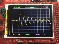
I bought one of those eighteen dollar oscilloscope kits on eBay, the "DSO138", and tried it out with Quasimodo and some transformers and some inductors. I found it to be a cute little electronic stunt and enjoyable hobby plaything, but not actually useful in combination with Quasimodo.
The thing simply isn't fast enough to digitize and display waveforms from real transformers with real snubbers. Although the claimed bandwidth is 200 kHz and the claimed sample rate is 1 Msps, I couldn't get it to trigger on nonperiodic signals even at much slower settings. It certainly won't display the ringing of a low-leakage-inductance toroidal transformer like the Antek AS-2222, which is used in many chip amps.
I did succeed in using DSO138 + Quasimodo to critically damp a 10 millihenry fixed inductor, as shown below. Unfortunately real transformer secondaries have leakage inductances a factor of ten thousand smaller than this. So the toy example below does not extrapolate into real world success on real world transformers. Too bad, it would have been fun to measure a $100 transformer with a $18 oscilloscope.
_
Attachments

I can't believe anyone would use a resistor only as a snubber
The goal is to snub the ringing and dissipate the least amount of power
Excessive snubbing will reduce the life and dynamics of any preamp
As for rectifiers you want low capacitance soft recovery and very low impedance
Schotkys I believe satisfy all of these refinements bit produce a very fast clean sound
However they rob the music of body
You cannot hear the body of an acoustic guitar
They are not very musical
I have yet heard one I would use
Hexfreds are preferred but sometimes they sound a little thuddy
I suspect this is from the higher vf
I can't believe anyone would use a resistor only as a snubber . . . The goal is to snub the ringing and dissipate the least amount of power
I think the goal of a snubber is to snub - i.e. get rid of the ringing associated with the LC resonance of transformers and other capacitance. Dissipating the least amount of power in the snubber is a design choice and orthogonal to the goal of snubbing.
Fglabach - you've been working hard to identify the sound of the various capacitors in the snubbing circuit. You of all people should be interested in a version that uses no capacitors at all! At the very least, it's useful as a listening reference to determine the effect of the capacitors on the sound.
---Gary
I can't believe anyone would use a resistor only as a snubber
The goal is to snub the ringing and dissipate the least amount of power
Excessive snubbing will reduce the life and dynamics of any preamp
As for rectifiers you want low capacitance soft recovery and very low impedance
Schotkys I believe satisfy all of these refinements bit produce a very fast clean sound
However they rob the music of body
You cannot hear the body of an acoustic guitar
They are not very musical
I have yet heard one I would use
Hexfreds are preferred but sometimes they sound a little thuddy
I suspect this is from the higher vf
I've decided to try the APT30S20B Schottky's Mark recommend. They'll be feeding some Sony VFETs which have a great reputation for being very musical. Hopefully they'll add to the Sony's virtues!
Regards,
Dan
I will be posting data on the Antek 6224 AN-6224 - 600VA 24V Transformer - AnTek Products Corp which will ultimately end up in my Pass Labs VFET2 http://www.diyaudio.com/forums/pass-labs/276711-sony-vfet-amplifier-part-2-a.html
I hope you decide to include some kind of "soft start" for the amplifier using that transformer; Nelson Pass usually recommends Inrush Current Limiters (great big NTC thermistors) in his amplifier designs. At powerup when the power supply filter capacitors are fully discharged, that 600VA transformer could conceivably deliver more secondary current than the diode's surge current max rating. Poof goes the diode. Murphy's Law says that your diode will fail before the primary fuse blows.
Have a glance at the Short Circuit Test values shown on the transformer spec sheet . Not a lot of copper resistance in that great big badboy, to limit current when charging up the filter capacitors.
I've built several of Nelson's amps and I've always followed his guidelines. So far I haven't had any issues when using the recommended inrush current limiter.
CL-60 Amphenol Advanced Sensors | Circuit Protection | DigiKey
5 amps steady state current?
Regards,
Dan
Last edited:
NTC Power Thermistors work very well for limiting starting current into transformers.
I recommend a relay bypass across the Thermistor to reduce the impedance seen by the transformer in normal operation, otherwise the NTC reduces AND varies the voltage fed to the transformer.
I recommend a relay bypass across the Thermistor to reduce the impedance seen by the transformer in normal operation, otherwise the NTC reduces AND varies the voltage fed to the transformer.
You need to do your homework with choosing an NTC. The device has to be rated to charge up your main filter caps, and cope with the PT in-rush, and cope with anything else that is being powered that has an in-rush surge (such as heaters in a valve amp).
The NTC datasheet provides the safe level of CVsquared, which you can reflect back to the mains voltage from your secondary side. But that safe level of in-rush energy also needs to accommodate PT inrush (which can be approximated).
I doubt you would notice the change in regulation with/without the NTC, as it has such a large resistance change. If your amplifier performance measurably/tangibly suffers then I'd be seriously considering looking for a better designed amplifier.
I reported some years ago the effect of watching the secondary voltage changing as the NTC varied it's resistance............................
I doubt you would notice the change in regulation with/without the NTC, as it has such a large resistance change. If your amplifier performance measurably/tangibly suffers then I'd be seriously considering looking for a better designed amplifier.
It's in one of the Krell clone Threads.
Andrew. I located:
http://www.diyaudio.com/forums/pass-labs/255523-recommendation-5-10w-amp-24.html#post4001806
which points to this:
http://www.diyaudio.com/forums/solid-state/78129-krell-ksa-100mkii-clone-173.html#post1265968
I searched for some technical detail on NTC impact and didn't locate anything relevant. Maybe I'm missing something - or was that thread intimating that some static measurement inconsistancy on output power level may be due to an NTC having a different operating temperature, and hence different resistance, and hence that would be more audible than all the other issues that seem to have surrounded the thread?
Well done, you found the 9 year old report !
Yes it was the in line NTC that varied it's resistance.
I should have bypassed the NTC and measured again. But I didn't.
I recall, but not in detail, seeing the way the clip changed as the secondary voltage changed when in ClassAB and when in ClassA. Getting the NTC hot as in ClassA removed some of the early clipping.
A PSU generally performs better when the Source Impedance is lower.
A Power Amplifier generally performs better when the source impedance (either the signal, or the power) is lower.
There are many impedance contributions along the path to the output stage of an amplifier. Without having information on all the impedance contributions, or the thermal time-constant of an NTC, or bringing in the effect of energy storage devices, or masking processes like feedback, makes a recommendation like relay bypassing a NTC a little off-handed.
Some interesting scope shots of secondary/diode currents versus differing rectifier/winding arrangements - https://diyaudioheaven.wordpress.com/tutorials/power-supplies/rectifiers/
It would be interesting to see scope shots of snubberised versions.


Dan.
It would be interesting to see scope shots of snubberised versions.
Dan.
Working together with an electrical engineer, your team might be able to replicate all of those scope measurements in LTSPICE circuit simulation. If you are successful then it would be straightforward to add various kinds of snubbers (2C+1R, 1C+1R, 0C+1R, 4C+4R, etc) to your simulation circuit, at various different choices of damping factor. The software will happily churn out all the data you want, whatever you want. And you don't needing a fancy laboratory setup including a $1000 current probe.
On the other hand, lots of people distrust simulations, even simulations which match physical measurements on actual hardware. If that bothers you then start saving money towards the purchase of a current probe 😉
On the other hand, lots of people distrust simulations, even simulations which match physical measurements on actual hardware. If that bothers you then start saving money towards the purchase of a current probe 😉
- Home
- Amplifiers
- Power Supplies
- Simple, no-math transformer snubber using Quasimodo test-jig