Scope Photos


The first picture is with .01 cap and .15 cap and 30 ohm resistor.
The second photo is when I increased the first cap from .01 to .022.
I have not done any listening yet
The first picture is with .01 cap and .15 cap and 30 ohm resistor.
The second photo is when I increased the first cap from .01 to .022.
I have not done any listening yet
The first photo has the high frequency squiggles some of you have talked about
Moving up from the .01 to the .022 first cap really improved the scope picture and I had no need to increase the .15 cap
Tonight I will find I will listen to the choices
Moving up from the .01 to the .022 first cap really improved the scope picture and I had no need to increase the .15 cap
Tonight I will find I will listen to the choices
I have a great deal of experience listenng to snubber crcuits. I know what they do and I know what to listen for.
Mark johnson is an incredibly intelligent enginner
Has anyone looked at his credentials!!!!
I may even buy vol 10 of Linear Audio to see the results of his soft recovery diode ringing test.
I would suggest that you want oversize rectifiers in current so they have super low impedance but the soft revoery feature I think creates more internal resistance.
Oversize voltage creates more capacitance and that is a bad thing soncially.
So you may get the best of both worlds with a high current fast welding rectifier like 80 amps and then snub the ringing with the quasimoto.
Thats what sounds best to me.
If Mark asks me nicely Ill tell him which vishay hyperfast welding recitifers sound the best
If you like the clean amusical sound of Shoktys then we have different listening biases.
But I defer to Mark here on rectifiers.
So I am a decent engineer a good listener and have a very great sounding expensive tube based audio system
Turntable source based of course.
Hear is what I heard
You only use the qusimotor to get your resistor value.
Then you are off to the listening.
First, the smaller cap opens up and cleans up the highs
You want dulled highs.
Stick in a low grade film cap and hear your highs dulled.
Mark is right, You can hear the dissipation factor of the cap. The lower the better
But what about the ESR?
In every listening tests we preferred two high grade film caps in series.
I suggest a very high esr is not good here.
Withe series same openess and less hardness in the highs.
Maybe you get to the same place with a very small resistor in series with one cap, but I have not tried it.
This can very easily blunt dynamics because the larger cap dissipates more power through the resistor.
The resistor cap combo blunted dynamics excessively. But it did create more body and take away tizziness in the midrange.
So lets go with the caps in series again and then the resistor.
Again better
I had to go down to .15 uf caps in series
Some Life and body but not quite enough life.
So down to two .1 uf caps in series. But now I still wanted a little more openess. I was unsure whether I wanted to give up dynamics by using it at all
So I went back to the untuned caps in series. I reduced the pair of .047uf to .022 in series. Now it had more life even with the tuned capacitor in place
Now I had both. Openness, less bluntedness, more body in the midrange and less tizziness.
Back and forth you must go.
And you need better caps that the epcos that Marc recommends.
I recommend the ATC polyprop caps from Allied Electronics. They are only about $3 each. Maybe the Wima FKP1. They sound good to me too.
I bet Mark would point out the untuned cap series pair is about .01.
while the resistor cap pair is about .05, which is too close together.
He suggest a 10 times minimum, but I have to go with my ears.
I am curious whether like a .1ohm resitor in series with a cap would sound better than two larger caps in series for the untuned cap. To my ear the esr of these high grade polyprops is just too low for snubbing and create more resonances.
I would love Mark to provide a scientific explanation for all this. But if he doesn't, it won't matter to me.
His Epcos .o1 and .15 cap were totally unacceptable sounding. AIf I had been limted to those, I would have agreed with Rick that you are better off with just a small cap acroess the secondary because then you are at least not blunting the dynamics.
This was a lot of work so I hope someone appreciates it.
Glad you found an arrangement that pleases you! Maybe your further engineering research will discover additional refinements that please you even more.
After reading your technical report above, it wouldn't surprise me at all if your future listening tests show that a power regenerator such as the PS Audio P10 adds another level of listening enjoyment.
On the other hand I remind myself that not all pieces of audio gear are vacuum tube preamps with linear power supplies. My new favorite example is the Sutherland 20/20 phonostage, which uses Switch Mode Power Supplies, enclosed in wall-warts (!), to convert mains voltage to 48VDC. I think it's unlikely that member fglabach's careful tweaks to his vacuum tube preamp power supply, would have the same effect upon an SMPS wall wart as used in the 20/20.
Mark I sense you think this is more about tweaking the sound than real science for me
I'd like to think there is some science behind what I do and my observations have application to more than my specific power supply
In any event the device you built save lots of time in getting where you want to go
I'd like to think there is some science behind what I do and my observations have application to more than my specific power supply
In any event the device you built save lots of time in getting where you want to go
Mark
I attached it to a large split bobbin transformer in circuit with 10000uf capacitance across the rectifiers
For the first cap I used a ,01uf
I can use any cap for the tuned cap
As I turn down the pot it gets better and better but never completely flattens out
If I lower the resistance further it creates new bumps
It's about a 33 ohm resistance
What's weird is that a .01 cap with the 33 ohm
Resistor works and if I increase it no better
I can reduce ringing but can't critically damp
Every time someone posts this request, I give the same answer: If you don't like or don't trust the no-math answer, your only alternative is to use math.
I suggest you begin this effort by measuring the leakage inductance of the transformer secondary (in Henrys) with each primary winding shorted and with each other secondary winding shorted. These shorts are shown as heavy black bars in Fig 13.d of the Quasimodo design note.
Once you know the measured value of the secondary leakage inductance, and once you know the values of Cx and Cs you will use to snub it, then you can calculate the value of Rsnub which gives zeta=1.0.
Have a look at posts #257 , #487 , and #703 here in this Quasimodo thread.
If you prefer to buy components from mouser.com , the thru-hole fixed inductors made by Sumida are excellent choices for your calibration and confirmation and get-comfortable exercises with Quasimodo. If possible, buy inductors with ±5% tolerance; they'll help you decide whether your tests are getting The Right Answer, or not.
If you buy components from digikey.com , the thru-hole fixed inductors made by Bourns are excellent choices for your calibration and confirmation and get-comfortable exercises with Quasimodo. If possible, buy inductors with ±5% tolerance; they'll help you decide whether your tests are getting The Right Answer, or not.
Remind yourself that many dozens of diyAudio members have built their own Quasimodo and used it successfully. It is possible. Other people have done it. Some of them are probably more experienced than you, and some of them are probably less experienced than you. This should comfort you.
Misunderstanding again
I have already used the quasimoto on 2 power supplies and it works wonderfully and I trust it.
Its just with this particular supply I can't get it to critically damp.
Thought you might have some suggestions.
I have no interest in doing the math again. I did it with the Hagerman article many years ago.
I don't trust these snubbers
I would try to avoid this snubbering approach... And find a way such that the snubbering is not necessary... That's my current conclusion.
I would try to avoid this snubbering approach... And find a way such that the snubbering is not necessary... That's my current conclusion.
Ron Sutherland has certainly found one way: wall wart SMPS, placed one meter distant from the analog electronics' chassis (link). Complete Galvanic isolation using photovoltaics is another. There are a couple more in the RCA Receiving Tube Manual, and I'm confident the best and brightest designers right here on diyAudio can disclose/invent additional ideas that can be implemented in finite man-hours on a limited budget.
_
_
Last edited:
i'm not sure i understand the intent of your comment?
it is the nature of how the parts function in the circuits' operation is that some ringing is created.
there is the question of the audible impact of such ringing, but if you reduce or eliminate the ringing, the audibility issue becomes irrelevant.
you can use soft recovery rectifiers, but that only reduces ringing.
if you decide you don't care about the ringing, then snubbering is not necessary.
🙂
mlloyd1
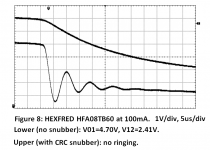
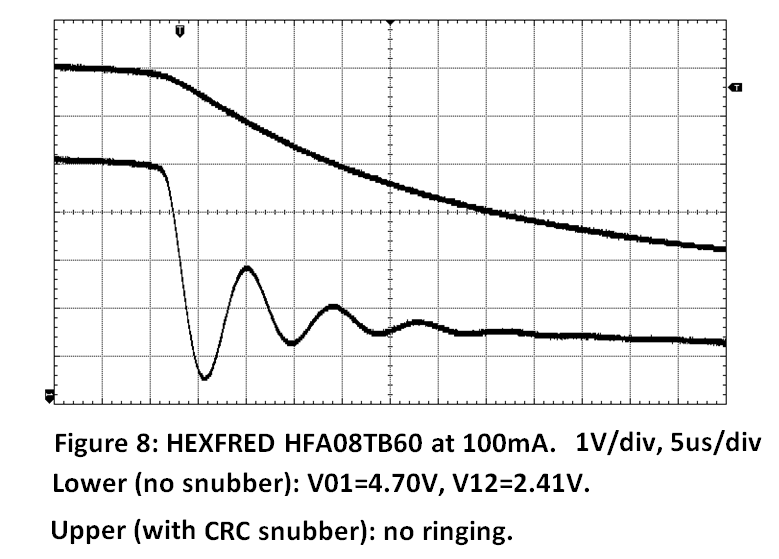
... you can use soft recovery rectifiers, but that only reduces ringing.
They all rang, even the HEXFREDs. Even the Schottkys.
Here's a HEXFRED photo:
_
_
Attachments
I read with care your explanations as to why the crc is preferred to the cr
However all of your considerations seemed practical
Isn't there a sonic advantage to having one low esr cap snub the high frequency noise and another tuned one to cancel the ringing frequency
I may be wrong but doesn't the crc raise the total capacitance which is not desired
Doesn't it also result in a lower value resistor that dissipates more power
I am afraid I am revealing my weak engineering skills here
I now have my Quasimodo V4 up and running and I just have to get my scope out. Many thanks to Mark for his generous gift of a great design and always friendly support.
Regards,
Dan 🙂
Regards,
Dan 🙂
Congratulations Dan! For additional huzzahs and props please post scope photos of your QM in action. Before and after shots, (i) Rs = Infinity, i.e., pot removed from socket; (ii) Rs = optimum, with ringing damped out.I now have my Quasimodo V4 up and running and I just have to get my scope out.
The great thing about Quasimodo is, you can use it however YOU want to. No Snubber Police are going to knock down your door, open up your DIY gear, and check whether you've built Approved And Orthodox snubbers. Do whatever you like!I may be wrong but doesn't the crc raise the total capacitance which is not desired
The Quasimodo design note even contains a section (pp. 12-13) that shows how to use QM to optimize a 1R+1C snubber if that's what you want to do.
I've gotten email from some pretty top notch EEs who tell me they are using QM to optimize a 1R+0C snubber (!!), namely, 1 resistor and zero capacitors. Maybe the sound of no capacitors at all, is more pleasingly euphonic than the sound of the best possible capacitor. In a snubber. May be! The only cost is a little more power dissipation.
If you listen carefully a low esr cx cap cleans up some high frequency noise from the broadband noise burst when the diodes snap off
The tuned larger cap actually affects the sound of the midrange and can clean up the background
You generally want to minimize dissipation as this drags down the openness of the music
Based on what I read to do the resistor snubber you sound use a very small injection cap
My approach is use Quasimodo for the initial resistor value
Then use combinations of caps for best sound
Large you have built the snubber with perhaps different size caps now retest for the right resistor value
Ron Sutherland has certainly found one way: wall wart SMPS, placed one meter distant from the analog electronics' chassis
How about the issue of long cable? Doesn't it invite interference that require something similar to snubbering in the analog chasis?
i'm not sure i understand the intent of your comment?
So soft recovery is preferred if this snubbering thing is to be avoided?
The intent of the comment is simply giving my conclusion from my experience using snubbers and other things. See below:
I've gotten email from some pretty top notch EEs who tell me they are using QM to optimize a 1R+0C snubber (!!)
Then these top notch EE must have found the negative side effect of the capacitors by trying to exclude the cap at all (it can't be because they think capacitor is expensive).
I'm not sure how this snubbering can ruin the sound (I prefer not to speculate when there are many experts around) but I can assure you that however and whenever I tried I have preferred the sound without (this requires at least one hour to listen. First few minutes listening, of course the snubbering is preferred).
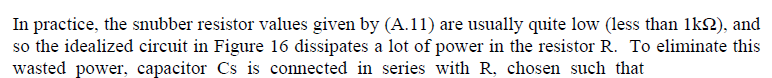
Naah, the 1R+0C snubber folks are extreme minimalists who feel that adding a capacitor merely to reduce the power consumption of the snubber (as explained in Quasimodo design note appendix A below), is silly. Omit the capacitor, eat the extra power, and take pride in your schematic which has fewer parts than the other guy's schematic. Fewer parts means more minimal. More minimal means more better -- to an extreme minimalist.
However it must have occurred to many readers that this is something which could, in principle, be adjusted by ear. If diyAudio member Jay is correct, that it takes at least two hours to perform a listening test, then a dedicated experimenter could try about two resistor settings per day. In five days he could try R=Infinity (i.e. no snubbing resistor at all, i.e. zero damping), and also try the resistor settings which give damping = 0.1, 0.2, 0.3, 0.5, 0.7, 1.0, 1.5, 2.0, and 3.0. Ten different snubbings, ten different listening sessions of two hours apiece. Maybe what the ear prefers, is not what pleases the eye on the face of an oscilloscope?
_
Attachments

Mark:
Yep, agreed! My comments were meant for the message just prior to yours.
🙂
mlloyd1
Yep, agreed! My comments were meant for the message just prior to yours.
🙂
mlloyd1
They all rang, even the HEXFREDs. Even the Schottkys.
Here's a HEXFRED photo:
_
_
- Home
- Amplifiers
- Power Supplies
- Simple, no-math transformer snubber using Quasimodo test-jig