Appendix D of the Quasimodo design note shows how to find the polarity "dots" of a transformer using lab bench test equipment. However, some QM users don't like this method for various reasons.
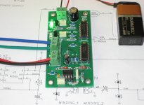
So, in response to their requests, I've designed and built a little standalone test jig which finds transformer polarity dots using no lab equipment -- just this little test jig and a 9V battery. It's three digital logic chips (555 timer, CD4070 exclusive OR gate, CD4069 inverter gate), a few passives, and two LEDs, as you can see in the picture below. When transformer winding dots are aligned, the green "IN PHASE" LED lights up. When transformer winding dots are misaligned, the red "OUT OF PHASE" LED lights up. Simple and unambiguous.
The schematic, PCB manufacturing CAD data ("Gerber files"), and bill of materials are found in (THIS diyAudio thread). I also have a few kits of PCB + all parts, which I'm selling at my cost.
Attachments
Hello guys! I have just built my Quasimodo. Ordered PCBs from Seeedstudio - perfect quality. But I have a question about film caps C1 & C4. When I was ordering all the parts using BOM from first post, C1 cap (connected to control voltage pin of LMC555) wasn't marked as film, so I bought X7R ceramic 1nF cap. Now, looking carefully at all the pictures of already built Quasimodos I see that most of you use film cap for C1. Does it make any difference if I use ceramic cap instead of film one for C1?
A film capacitor is likely yo have lower esr than the X7R.
This extra damping resistance will have a small effect on the final damping resistance that you measure and then implement.
The difference may be too small to measure and thus can be ignored.
However, if your implementation also uses an X7R, then the measured damping resistor and the esr are BOTH needed to arrive at the optimal damping arrangement.
Can you get the X7R in suitable voltage ratings to suit all your circuits?
Andrew, I'm going to use film caps for CRC snubber. C1 is not a snubber cap - it's the cap for CMOS timer and have nothing to do with CRC snubber (C2=CX, RV1=RS, C3=CS).
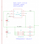
Atnegam, the bypass capacitor from 555 pin#5 ("control voltage") to ground, is utterly non-critical. There's disagreement over whether it's truly necessary, or just common folklore / voodoo about 555s. The supposed "reason" why people install it, is to make pin#5 impervious to capacitively coupled noise injection from nearby components. The reason why I installed it, is because I didn't want to listen to whiny people complain about its absence. Any capacitor at all, made of any dielectric at all, with any temperature coefficient at all, will be just fine in that position.
However the timing capacitor from pins 2+6, to ground, is quite a bit more important. This capacitor, called "C4" in the schematic below, sets the oscillator period, along with whichever pieces of R3,R4,R5 are selected by the dip switches. I would recommend using a better-than-average capacitor type for C4. Either metallized film, film, C0G ceramic, or X7R ceramic.
C4 is not super-critical, since the way we actually use Quasimodo only looks at a single waveform edge and not a full period (or many full periods) of the square wave. Therefore, if the oscillator's frequency wanders around*, Quasimodo users don't care. (Indeed they won't even see it). So my suggestion to you is: don't worry about it. Use your Quasimodo and have some fun. Be sure to read the section "Triggering the Oscilloscope" on page 12 of the QM design note.
*perhaps due to C4 variations with temperature, or C4 variations with supply voltage, or C4's value simply drifting up and down over time
_
Attachments
Mark, thanks for the comrehensive answer! I use Epcos metallized polyester film capacitor with 5% capacitance tolerance for the C4. And I think it's pretty suitable for the C4's role that you have described.
An article I wrote for the just-announced Linear Audio volume 10 (link), may be of interest to Quasimodo users. Its title is "Soft Recovery Diodes Lower Transformer Ringing by 10-20X." A very brief preview of the article is available on the web page linked above; scroll down to "Articles in this volume" and then click "preview".
sounds interesting mark.
that's one of the reasons i'm buying this issue.
i look forward to reading your article!
mlloyd1
that's one of the reasons i'm buying this issue.
i look forward to reading your article!
mlloyd1
Mark Johnson,
🙂 Thanks sharing your documented findings for Quasimodo test-jig and the new article, seems HQ and value free for us diy'ers we just need to grab it.
🙂 Thanks sharing your documented findings for Quasimodo test-jig and the new article, seems HQ and value free for us diy'ers we just need to grab it.
Does anyone have a fully assembled Quasimodo board to sell? How about a bare Quasimodo board plus kit of all parts, to sell? If so then diyAudio member marsupialx would be thrilled if you sent him a Private Message.
Phasedot $13 Quasimodo unavailable. Watching PM. Thanks. Let me know where to send cash.
PM sent 🙂
I'm working on a low noise power supply for one of my phono preamps.
It will use a couple of Hammond 229D40 transformers acquired from Mouser
Just wanted to share my snubber values in case anyone else finds them useful:
0.15uF, 0.01uF and 424ohms (I happened to have a bunch of 196 ohm and 226 ohm resistors so the "weird" value is not a problem).
Thanks again Mark for your handy design!
mlloyd1
Congratulations Mlloyd1, glad you got your Quasimodo up and running. Thank you for mentioning your optimum values, diyAudio member DNi may wish to add this datapoint to his Excel table in post #643.
Does anyone have a fully assembled Quasimodo board to sell? How about a bare Quasimodo board plus kit of all parts, to sell? If so then diyAudio member marsupialx would be thrilled if you sent him a Private Message.
Please see the post 554. I have kits available.
Mark:
That was a well done article in LA. The test results and rankings (you're a brave guy 🙂) are much appreciated. I do have to say I'm glad I got my parts before your ratings drive the prices up!
mlloyd1
That was a well done article in LA. The test results and rankings (you're a brave guy 🙂) are much appreciated. I do have to say I'm glad I got my parts before your ratings drive the prices up!
mlloyd1
Thank you for the kind words, Mlloyd1! I could have saved a lot of money if I had bought each of those 48 diodes by using Octopart.com parts search engine to find the lowest (qty=1) price; AND I recommend this procedure to all readers. Besides reaping significant savings, octopart gives you the chance to get out of your boring old repetitive purchasing rut, and buy from a new distributor you've never used before.
But that's only what I wish I had done. In actual fact I bought a few diodes here and there, at random, tacked on to other orders, without any grand unified plan except "Oooh look at the shiny new parts!" When my bucket had filled up to four dozen candidates, I decided enough was enough, let's measure and choose. I optimized convenience when buying, rather than cost.
By the way I am a little jealous of you; my copy of v10 has not arrived yet!
Last edited:
First of all:
Thanks Mark for this great piece of work and thinking! I've read here for a long time, actually quite after you started this thread, but never wrote anything.
Now my question:
Does anybody sell 1 or 2 pcbs in Europe or Brasil? Kits are also fine! 🙂
All the best,
Matthias
Thanks Mark for this great piece of work and thinking! I've read here for a long time, actually quite after you started this thread, but never wrote anything.
Now my question:
Does anybody sell 1 or 2 pcbs in Europe or Brasil? Kits are also fine! 🙂
All the best,
Matthias
- Home
- Amplifiers
- Power Supplies
- Simple, no-math transformer snubber using Quasimodo test-jig