While more examples could be useful, you might also consider cross-checking the results obtained when dialing the Rs trimmer until a damped pattern is obtained, by using a method that combines the ringer with a calculation formula.
I'm enclosing an Excel sheet which summarizes my experience from using the Quasimodo ringer on ten different transformers. The sheet contains also the formula for calculating an optimal snubber proposed in the paper by Hagerman (referenced by Mark in an earlier post). In order to apply the formula, one must know the ringing frequency with only Cx in place, and (optionally) the resistance of the secondary winding. The frequency can be determined from the free oscillatory response of the secondary when ringed by Quasimodo. If one is lucky to have a digital scope with cursors, it can be read off the screen directly; otherwise it can be obtained by counting the graticules on the screen to determine the signal period.
Having obtained the resonant frequency, simply enter it into the corresponding green cell in the sheet (E16 in my case), enter the secondary winding resistance into cell D16, and the value of the snubber resistor for the damping factor Zeta given in cell G3 (currently Zeta=0.707) pops up for you in cell J16 of the sheet. The value of Zeta in the sheet can be changed at will.
A value Zeta=1.0 has been recommended by Mark several times, and it one that makes sense. The reason why my table was done with Zeta=0.707 is that at the beginning I tested a couple of transformes with this value, and was lazy to redo the measurements with Zeta=1.0 later.
As it is, the last line in the sheet merely repeats the case in the row above (the Era transformer) for demonstration purposes.
Apparently, the agreement between the Rs values obtained by pattern matching and those calculated on the basis of the natural (resonant) frequency is good in most of the cases. There always will be difficult transformers, and especially in such cases it is not bad to have two methods for determining the snubber resistance.
Regards
Hi DNi, thank you for such detailed and informative massage. I also used some XLS that I made based on Jim's article. However, Quasimodo should give us a visual answer with no math. So, I would like to see some pictures of scope screen when R in close to idle but under, close to idle but over and what is exact idle behave. So, it is should work as a kind of pattern recognition in our eyes....
I understand the idea of snubbing. The pdf on the first page was quite nice on it.
My question was based in that with the quasimodo guideline values, we are using capacitors that within reason will swamp the capacitance shown by the closing rectifying diodes, or at least make it irrelevant.
To rephrase what I said, we are snubbing the secondary for use with a rectifier
What I was wondering was if we have any clues if those guideline values would be adequate for use with rectifying tubes. I have no idea what capacitance those might show to the secondary
If anyone would like to prepare a set of graphs showing Quasimodo waveshapes at several different values of the damping factor Zeta, there are resources here on the diyAudio website that can help you with the job.
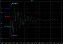
HERE is an LTSPICE simulation file (.asc) of a Quasimodo board in operation. It drives an inductor whose inductance value YOU choose. You can simulate exactly the Zetas you desire, simply by using the damping factor equations from the Quasimodo design note (A.10 and A.11) to select the appropriate snubber resistances which give those Zetas. Then you use LTSPICE's .STEP PARAM feature to overlay those several waveforms on the same output plot. I have attached an example below, showing five .STEPped PARAM circiuts on the same plot.
OVER HERE is a table showing how the ringing frequency varies as a function of the inductance connected to Quasimodo. You can use this table to extract the inductance of an unknown sample (such as a transformer), or you can run Quasimodo with a known, fixed inductor, and compare your measured ringing frequency against the table's frequency. This verifies that your Quasimodo board is working correctly. Once you know the inductance connected to Quasimodo, you can use equations (A.10 and A.11) to calculate the Rsnub value for any particular Zeta you desire. Run Quasimodo at that Zeta, snap a picture, and put it in your gallery. Repeat for as many different Zeta values as you wish.
And OVER THERE is DNi's spreadseet which calculates R for a given Zeta, or Zeta for a given R -- saving you from the tedium of punching in all the terms, factors, and coefficients of equations (A.10 and A.11).
_
Attachments
Is there a place that records the sound effect of critical (or other) snubbing the transformer secondary?
Has any body recorded any benefits of applying 'correct' secondary snubbing to their systems?
I myself find the effect is a lot 'smoother' sound with less fatigue plus added 'punch' and depth to the sound - overall, a rather beneficial simple technique to apply to any power supply.
Has any body recorded any benefits of applying 'correct' secondary snubbing to their systems?
I myself find the effect is a lot 'smoother' sound with less fatigue plus added 'punch' and depth to the sound - overall, a rather beneficial simple technique to apply to any power supply.
its not contradictive. I myself prefers quite alot of distortion before im finished with my sound. Yes thats right. I prefer distortion, and alot of it. I just hate to listen to undistorted stuff. You do to. You just dont know it.
I have submitted a question to the VALVES section of this diyAudio website; here it is (at this link). Please feel free to take ownership of this new discussion thread, and to steer the valve experts towards YOUR specific questions and doubts.... values would be adequate for use with rectifying tubes. I have no idea what capacitance those might show to the secondary
Snubbing a vacuum rectifyer is more likely to give more problems then it might be there to solve. Anode to cathode capacistance is dimensions away from the secondary in HV-trannys.
Thanks to Mark for coming up with such a nice tool.
I just got the Quasimodo V4 kit from dsolodov. Thanks, dsolodov! I spent the last hour and finished soldering the kit. It should now be ready for use.
I have a question. Attached is the power supply I use. This is the same as the "Center Tapped Secondary" in Mark's note.
The difference is that I use 22nF across each of the 4 diodes C3, C4, C5 and C6. This has been implemented in my existing PCB.
So what is the value of C2 in this case? Let us assume that Ct as well as Cd can be ignored. Of course, C3, C4, C5 and C6 with value of 22nF cannot be ignored.
P.S. I am a late comer and I have not read through this long thread. If this has been asked before please execuse me. I would be glad to use 10nF for Cx and 150nF for Cs but some of my boards already use 22nF.
Attachments
Last edited:
Are there any circuit theorists reading the thread, who want to answer HiFiNutNut's question?
Or for simulation lovers, Q3: How could you find the answer to question Q1 through the use of SPICE simulation?
Q1: If a center tapped transformer drives a four-diode bridge rectifier (to generate +Vout and -Vout), AND if each diode in the bridge has a 22nF capacitor in parallel, what is the correct value of Cx, the capacitance which resonates with the secondary leakage inductance? Plausible answers might include 5.5nF, 11nF, 22nF, 44nF, and 88nF. But what's the actual answer? And why? (assume Ctrafo << 22nF and also assume Cdiode << 22nF)
Or for those more practically inclined, Q2: Can you describe a laboratory procedure which answers question Q1 experimentally?
Or for simulation lovers, Q3: How could you find the answer to question Q1 through the use of SPICE simulation?
OK, I asked the original question. Maybe I should answer my own question.
It should be 44nF which is Cx1:22nF + C3/C4:22nF = 44nF if according to the above schematic. This is because for each secondary winding that has a separate CRC snubber, only one of the 2 connected diodes conducts at any one time, and while one is turned on the other is turned off. Snubbing takes effect when the diode suddenly turns off. When the diode turns off, its capacitance is effectively in parallel to Ct and Cx.
I asked the question because I wanted to have my understanding checked and be sure I put in the right C2 on the Quasimodo jig.
Let me know if I am wrong.
Last edited:
have an interesting question for those more savy them I....why cant you drive the primary with 60 cycle square wave and scope the secondary apply network until no ring?
my kit from our friend dmitry should be coming soon!
my kit from our friend dmitry should be coming soon!
That's a signal generator, a transformer, and an adjustable snubber. One component fewer than Quasimodo ExtraLight in post#561 of this thread. Give it a try, maybe you will be pleased with its performance. I recommend you arrange not to push any net DC current through the transformer winding, just in case there's any possibility of magnetizing the core. So I recommend either setting the signal generator to output a bi-level square wave, that alternates between +V and -V, or else AC coupling the generator to the primary, via a series capacitor.
If you've got a new modern arbitrary waveform generator, you could tell it to output a waveform with even more high frequency content than a square wave. Dust off the Fourier Analysis textbook, find the series for a square wave, boost the 5th thru 35th harmonics, transfer the waveform to the time domain, and then tell your AWG to generate that. Woo baby.
If you've got a new modern arbitrary waveform generator, you could tell it to output a waveform with even more high frequency content than a square wave. Dust off the Fourier Analysis textbook, find the series for a square wave, boost the 5th thru 35th harmonics, transfer the waveform to the time domain, and then tell your AWG to generate that. Woo baby.
Member HiFiNutNut asks an interesting question in post #608 above.
Suppose that, for some reason, a linear power supply includes a bridge rectifier where each of the 4 diodes in the bridge, has a capacitor of value C farads connected in parallel with the diode. All four diodes are identical and all four capacitors are identical.
HiFiNutNut asks: how do these four capacitances add, subtract, multiply or divide, to give an equivalent across-the-secondary capacitor "Cx" that resonates with the secondary leakage inductance?
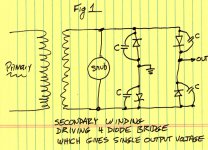
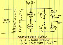
There are two cases to consider, shown below in Fig.1 and Fig.2. Fig.1 shows a single, 2 terminal, secondary winding driving the four diodes and four capacitors. This produces a single DC output voltage. Fig.2 shows a 3 terminal, center tapped, secondary winding driving the four diodes and four capacitors. This produces two DC output voltages, a positive output and a negative output.
And here are the answers:
_
Suppose that, for some reason, a linear power supply includes a bridge rectifier where each of the 4 diodes in the bridge, has a capacitor of value C farads connected in parallel with the diode. All four diodes are identical and all four capacitors are identical.
HiFiNutNut asks: how do these four capacitances add, subtract, multiply or divide, to give an equivalent across-the-secondary capacitor "Cx" that resonates with the secondary leakage inductance?
There are two cases to consider, shown below in Fig.1 and Fig.2. Fig.1 shows a single, 2 terminal, secondary winding driving the four diodes and four capacitors. This produces a single DC output voltage. Fig.2 shows a 3 terminal, center tapped, secondary winding driving the four diodes and four capacitors. This produces two DC output voltages, a positive output and a negative output.
And here are the answers:
If each of the capacitors is "C" farads, then Fig.1's effective across-the-secondary capacitance Cx is (1.0 x C) farads.
If each of the capacitors is "C" farads, then Fig.2's effective across-each-secondary capacitance Cx is (2.0 x C) farads.
I imagine that one or more people may now tut "well of course the answers are 1C and 2C, that's obvious by inspection!" ... yet they didn't mention this obvious answer until just now. If each of the capacitors is "C" farads, then Fig.2's effective across-each-secondary capacitance Cx is (2.0 x C) farads.
_
Attachments
Why do we not consider the effect of the smoothing caps that came after the rectifying bridge when we are analysing the TX secondary ?
I guess I could look at your circuit / drawing this way.
In your drawing, POS and NEG can be assumed to be short to ground for the resonant frequency because of the (not drawn) large reservoir caps. So the secondary wire (other than the centre tap) is effectively connecting to two capacitors (C) which are connecting to ground when the diodes are turned off.
Am I understanding it correctly?
If so, the Cx in my original schematic would be 3 x 22nF = 66nF.
Another question, or observation.
I have used the jig to come up with the snubbers for two transformers. It seems that the resonance is quite sensitive to the resistor values. i.e. even if I turned the trimpot slightly either way, the ideal response is gone within a turn or two. This behavior is not like LTSpice simulation, which appears to be far more tolerent to the resistor value.
For one transformer, I got close result with simulation. For the other, not so close.
What is your experience?
I'm still quite a newby, so I'd like some help.
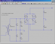
As a practical example, I've included the schematic of the DIY Universal PSU v3.
In the diagram, there are CX and Cs/Rsr. Cs and Rs are responsible for damping the ringing, Rs determining the damping factor, if I'm correct. But what is the purpose (and value) of Cx? I understand that Cs must be of such a value that the ringing frequency is easily passed and (much) lower frequencies are blocked. But where is the ringing signal passed to? Is it shorted to the negative side of the transformer, through the resistor? It's not shorted to ground...
Also, I can't figure out the purpose of C17/C18 and R11/R12.
Can Cs and Cx be any (small) value film- or ceramic capacitor, or does their value and type depend on the inductance of the secondary transformer coil? 😕
And to what capacitors do Cx and Cs relate in the Quasi/CheapoModo circuit?
The more I read about this, the more I seem to not understand. And I'm trying hard to stay motivated and not get overwhelmed by too much information...
Attachments
Last edited:
The right answer for the schematic in post#608 is Cx = (2 * 22nF) = 44nF. That's what you'd use in Quasimodo testing of the transformer secondary. When you install the snubber you'd let those four capacitors work together to produce 44nF across the secondary, and you'd include an additional ZERO nanofarad Cx capacitor in your snubber.If so, the Cx in my original schematic would be 3 x 22nF = 66nF.
There are three ways you can confirm or refute this answer: (i) pencil and paper analysis using Laplace Transforms; (ii) laboratory measurements of real power supplies; (iii) simulation. If you've got grave doubts about the right answer 44nF above, and if it is very important to you, then you can get busy with (i) , (ii) , or (iii) .
Last edited:
Could you show your analysis here? Does simulation agree with it?Why do we not consider the effect of the smoothing caps that came after the rectifying bridge when we are analysing the TX secondary ?
If you're unhappy with the results from no-math "dial it by eyeball" snubber optimization, then it's time to use math.... For one transformer, I got close result with simulation. For the other, not so close.
Extract the secondary leakage inductance "L" from the observed oscillation frequency, when you're running your transformer on Quasimodo with an accurately known "Cx" and with "Rs" removed from its socket (infinity ohms). This uses math.
Then calculate the theoretical value of Rsnub which will give Zeta=1.0, with your extracted secondary leakage inductance "L", your accurately known Cx, and with a Cs that permits good snubbing (Cs >= 15*Cx). This also uses math.
Then connect your trimmer potentiometer to your ohmmeter (short pin 1 to pin 2!) and set your trimpot to the calculated Rsnub which theoretically gives Zeta=1.0. Plug it in to Quasimodo, fire it up, and have a look on the oscilloscope. If you're pleased with the results, the job is now done. If you're not pleased with the results, it's time to hire a consultant to help you find what you did wrong. Or to tell you that your transformer is merde .
- Home
- Amplifiers
- Power Supplies
- Simple, no-math transformer snubber using Quasimodo test-jig