Introducing: Quasimodo ExtraLight
Revision A of the Quasimodo design note describes a test jig that Rings The Bell of a resonant circuit, by injecting a voltage step. The voltage step is provided by an ultra low-Z pulse generator whose output is a MOSFET having RDSon < 10 milliohms.
I'm sure I am not the only person who has wondered, why not turn the idea inside out? Why not Ring The Bell by injecting a current step instead of a voltage step?
Would it work? Would it be simple and cheap to build?
So I tinkered in the lab for a couple hours today, and I can report, the answers are yes and yes. It works fine and it's extremely simple to build. I hereby dub the idea
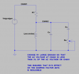
The "trick" is a simple observation: a high value resistor in series with a voltage source, gives a pretty fair approximation of a current source. In the schematic below, a signal generator or function generator acts as the voltage source. It outputs 120Hz square (voltage) waves, which R1 converts into 120Hz square (current) waves.
These current injections stimulate the transformer secondary and the snubber. The human operator dials the value of potentiometer Rs to get perfectly snubbed waveforms, without using any math. Just like Quasimodo.
I plugged together a little example on my solderless breadboard and generated oscilloscope photos labeled Fig1 thru Fig5 below. The darn thing really did work!
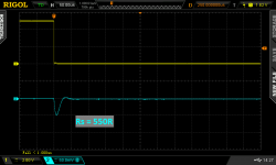
As you can see, the pulse generator's output was a 5.0 volt voltage step-down on node CHAN1 (yellow scope trace). In my setup, R1 was 33Kohms, which gave a 100 millivolt step-down on node CHAN2 (blue scope trace). 100 millivolts is 2% of 5.0 volts, so I think R1 has negligible effect upon the damping factor Zeta of the resonant circuit.
Eagle-eyed readers will no doubt see the little "B" in the Channel2 (blue) marker, indicating that I selected 20 MHz Bandwidth Limit for channel 2. This cleans up the display without distorting the sub-1MHz signal waveforms.
Mark Johnson
Revision A of the Quasimodo design note describes a test jig that Rings The Bell of a resonant circuit, by injecting a voltage step. The voltage step is provided by an ultra low-Z pulse generator whose output is a MOSFET having RDSon < 10 milliohms.
I'm sure I am not the only person who has wondered, why not turn the idea inside out? Why not Ring The Bell by injecting a current step instead of a voltage step?
Would it work? Would it be simple and cheap to build?
So I tinkered in the lab for a couple hours today, and I can report, the answers are yes and yes. It works fine and it's extremely simple to build. I hereby dub the idea
Quasimodo ExtraLight
The "trick" is a simple observation: a high value resistor in series with a voltage source, gives a pretty fair approximation of a current source. In the schematic below, a signal generator or function generator acts as the voltage source. It outputs 120Hz square (voltage) waves, which R1 converts into 120Hz square (current) waves.
These current injections stimulate the transformer secondary and the snubber. The human operator dials the value of potentiometer Rs to get perfectly snubbed waveforms, without using any math. Just like Quasimodo.
I plugged together a little example on my solderless breadboard and generated oscilloscope photos labeled Fig1 thru Fig5 below. The darn thing really did work!
As you can see, the pulse generator's output was a 5.0 volt voltage step-down on node CHAN1 (yellow scope trace). In my setup, R1 was 33Kohms, which gave a 100 millivolt step-down on node CHAN2 (blue scope trace). 100 millivolts is 2% of 5.0 volts, so I think R1 has negligible effect upon the damping factor Zeta of the resonant circuit.
Eagle-eyed readers will no doubt see the little "B" in the Channel2 (blue) marker, indicating that I selected 20 MHz Bandwidth Limit for channel 2. This cleans up the display without distorting the sub-1MHz signal waveforms.
Mark Johnson
Attachments

Thanks sharing, counts fewer and fewer parts last one difficult to beat 🙂......Quasimodo ExtraLight.....
I note Vishay soft recovery diodes VS-HFA08TB60PbF, VS-HFA15TB60PbF. The datasheets provide typical rates of current change during ta and "peak rate of fall of recovery current during tb".My personal decision has been to buy from manufacturers who (a) measure, and (b) specify, and (c) guarantee this soft-recovery parameter. Fairchild is one (example); notice the sortable column called tb/ta.
Last edited:
ExtraLight - top effort Mark.
That would be amazingly easy to set up and use, especially with many vintage lab signal generators sourcing up to 30Vpp square-waves with transitions well below 100ns.
That would be amazingly easy to set up and use, especially with many vintage lab signal generators sourcing up to 30Vpp square-waves with transitions well below 100ns.
Mark,
could you add some pics of impulse and reaction to the five you already have?
Show what it looks like with Rsnubber @ 270r, 130r, 68r, 0r0?
could you add some pics of impulse and reaction to the five you already have?
Show what it looks like with Rsnubber @ 270r, 130r, 68r, 0r0?
Naturally, Quasimodo ExtraLight has a few drawbacks and disadvantages.
First, the output signal CHAN2 is small, less than 100 millivolts. It is easily corrupted by noise from the much larger signal swing on CHAN1. I found it helpful to engage the (BandwidthLimit = 20MHz) feature of my scope, to get rid of some of this grunge. Even with this engaged, it's a struggle to get a nice waveshape on the scope.
Second, the ExtraLight circuit does in fact squirt a small amount of DC into the transformer. (Quasimodo, being capacitor coupled, does not and can not inject DC). In most cases this is completely unimportant ... but, if you're playing with a super expensive, small, hand-built device from Jensen Transformers, you don't want ANY possibility of magnetizing the core or altering its characteristics. Not even 5V/33K = 152 microamperes of direct current.
Third, the ExtraLight circuit does not require Cx (unlike Quasimodo, which uses Cx as its injection port). This permits people to dial-in an optimum single-C, single-R snubber, rather than the 2C+1R "CRC" snubber that I prefer. I consider this a bug; no doubt Morgan Jones {a proponent of single-C, single-R snubbers} considers it a feature 😉
Nah, it's already torn down. Feel free to do this yourself if you like ... BUT ... beware: you'll be venturing into the territory of very Very small signals as you decrease the Q and increase the Zeta. Your scope trace will turn into mush sooner than you'd like.Mark,
could you add some pics of impulse and reaction to the five you already have?
Show what it looks like with Rsnubber @ 270r, 130r, 68r, 0r0?
I recommend using whichever of your signal generators has the largest amplitude square wave output. The mid-priced ATF20B will put out 20V; 2% of that is 400mV which might, just might, be enough to experiment with low Qs and big Zetas.
Or just hook up a regular Quasimodo to an 18V power supply, you'll get all the signal in the world.
I'm thinking about revising the Quasimodo design note. More than a year has gone by since revision A, and quite a few people have built and used a Quasimodo.
Watching people play with their Quasimodos, I've noticed a tendency, especially among those who have no prior experience with damped second order linear systems. They get the notion that the optimum value of the damping factor Zeta, is Infinity. "If some is good then more is better!" And so they crank down their Rs potentiometer until oscillations disappear, then they keep on cranking. Yes it's damped, yes the oscillation's gone, but shoot dang, let's crank it some more!
Instead of trying to convince people not to follow their natural instinct, I think what I may do is arrange for this over-enthusiastic over-cranking, to do less harm than before. I think I might make a couple of tweaks to my recommended "how to snub your transformer using Quasimodo" instructions, so that the safety zone where all-is-well, gets considerably larger than before.
I did a few experiments this afternoon, using a Quasimodo V.4 board, to see whether my goal of "over-cranking should be less harmful" was achieved. With a couple of reservations, I think it was, for the most part.
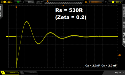
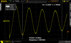
I used a 100 microhenry inductor (L measured with an Agilent RLC meter) for testing. The across-the-secondary capacitor Cx was 2.22 nF (also measured with the Agilent meter). Series capacitor Cs was 2.0 microfarads, and 25-turn trimmer potentiometers (1K and 50R) were used to set the snubbing
resistance Rs.
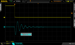
As a double check, the undamped oscillation frequency should, according to EE theory, be 1/(2*PI*sqrt(L*C)) = 338 kHz. On the lab bench, the measured frequency was 338 kHz (Fig01).
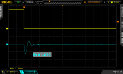
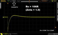
The value of Rs which gives critical damping (Zeta = 1.00), for this L and for this C, is 0.5*sqrt(L/C) = 106.1 ohms.
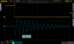
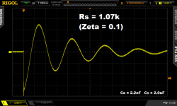
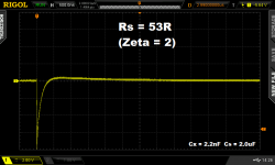
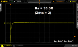
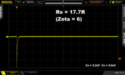
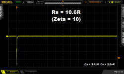
Nine different Rs resistance values were dialled in, from 1.07K to 2.00R, corresponding to (Zeta=0.1) to (Zeta=53). These are shown in Fig02 thru Fig10.
Large values of resistance / low values of Zeta, were plotted at 1.0 usec per division. Then at Zeta=1.0 the timescale was zoomed-in to 500 nsec per division, to make the first part of the overdamped waveform easy to see.
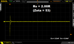
The waveforms were well behaved all the way up to Zeta=10, but eventually Rs became too small compared to the capacitive reactance of Cs. Somewhere between Zeta=10 and Zeta=53, the damping stopped improving and started getting worse instead. Since the goal is to achieve Zeta = 1.00 or maybe a little bit higher, this provides rather a gigantic safety margin.
I'm still deciding what to recommend or not recommend for revision B, but the data here suggests that plenty of additional cushion is available to protect people from their naturally over-enthusiastic over-cranking.
Watching people play with their Quasimodos, I've noticed a tendency, especially among those who have no prior experience with damped second order linear systems. They get the notion that the optimum value of the damping factor Zeta, is Infinity. "If some is good then more is better!" And so they crank down their Rs potentiometer until oscillations disappear, then they keep on cranking. Yes it's damped, yes the oscillation's gone, but shoot dang, let's crank it some more!
Instead of trying to convince people not to follow their natural instinct, I think what I may do is arrange for this over-enthusiastic over-cranking, to do less harm than before. I think I might make a couple of tweaks to my recommended "how to snub your transformer using Quasimodo" instructions, so that the safety zone where all-is-well, gets considerably larger than before.
I did a few experiments this afternoon, using a Quasimodo V.4 board, to see whether my goal of "over-cranking should be less harmful" was achieved. With a couple of reservations, I think it was, for the most part.
I used a 100 microhenry inductor (L measured with an Agilent RLC meter) for testing. The across-the-secondary capacitor Cx was 2.22 nF (also measured with the Agilent meter). Series capacitor Cs was 2.0 microfarads, and 25-turn trimmer potentiometers (1K and 50R) were used to set the snubbing
resistance Rs.
As a double check, the undamped oscillation frequency should, according to EE theory, be 1/(2*PI*sqrt(L*C)) = 338 kHz. On the lab bench, the measured frequency was 338 kHz (Fig01).
The value of Rs which gives critical damping (Zeta = 1.00), for this L and for this C, is 0.5*sqrt(L/C) = 106.1 ohms.
Nine different Rs resistance values were dialled in, from 1.07K to 2.00R, corresponding to (Zeta=0.1) to (Zeta=53). These are shown in Fig02 thru Fig10.
Large values of resistance / low values of Zeta, were plotted at 1.0 usec per division. Then at Zeta=1.0 the timescale was zoomed-in to 500 nsec per division, to make the first part of the overdamped waveform easy to see.
The waveforms were well behaved all the way up to Zeta=10, but eventually Rs became too small compared to the capacitive reactance of Cs. Somewhere between Zeta=10 and Zeta=53, the damping stopped improving and started getting worse instead. Since the goal is to achieve Zeta = 1.00 or maybe a little bit higher, this provides rather a gigantic safety margin.
I'm still deciding what to recommend or not recommend for revision B, but the data here suggests that plenty of additional cushion is available to protect people from their naturally over-enthusiastic over-cranking.
Attachments

Last edited:

Ah !
you had to take Zeta>>10 to get the ringing back.
Does that mean that zeta >0.5 and zeta <10 would be a range for an acceptable R value that is still near optimal?
Or would you say I am reading too much into those results?
you had to take Zeta>>10 to get the ringing back.
Does that mean that zeta >0.5 and zeta <10 would be a range for an acceptable R value that is still near optimal?
Or would you say I am reading too much into those results?
Last edited:
Might be fun to fit a rotary switch with differing Zeta value resistors and run a listening test.
Dan.
Dan.
Yes, already done and also done by swapping.Might be fun to fit a rotary switch with differing Zeta value resistors and run a listening test.
Dan.
Putting in a zero resistor value or a far too low resistor value brings back the ringing.
The question in my head came down to:
How low is "too low".
Zeta =53 is now confirmed as "too low" for the resistor value.
Did you note subjective effects in the ranges of no snubbing/optimal snubbing/over damped ?.
Dan.
Dan.
"It is impossible to make anything foolproof, because fools are so ingenious." -- Robert A. Heinlein
It is now possible to make a CRC snubber arrangement that operates correctly when fools set it to Zeta=10, even though the documentation strongly recommends Zeta=1.0. However, if an especially ingenious fool sets it to Zeta=53, the result is, predictably, disappointment.
It is now possible to make a CRC snubber arrangement that operates correctly when fools set it to Zeta=10, even though the documentation strongly recommends Zeta=1.0. However, if an especially ingenious fool sets it to Zeta=53, the result is, predictably, disappointment.
The shipping to most European countries is $9.45 by USPS First Class International Mail vs $2.32 to the lower states in the United States. Please PM your e-mail for an invoice.
Are there still boards available?
OK... I thought I had to PM you... is "dsolodov" the correct forumname?Please contact dsolodov.
- Home
- Amplifiers
- Power Supplies
- Simple, no-math transformer snubber using Quasimodo test-jig