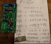
Unfortunately that is not correct. To get the correct answer I recommend you perform the calculation using amps instead of milliamps:... ~230uA RMS (+/-329uA) across Rs so I assume that's .23*.23*12.5 = 0.66mW ...
(2.3E-4 amps) x (2.3E-4 amps) x (1.25E+1 ohms) = 6.61E-7 watts. A factor of a thousand smaller than "0.66mW".
Can anyone point a target value for RC values to use in a 36V tx secondary ?
I am having trouble with my build and would like to have some indicative ballpark
I am having trouble with my build and would like to have some indicative ballpark
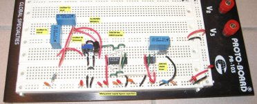
You can build a temporary "CheapoModo" (link to thread here) , even on a solderless breadboard. See image below. That's the first prototype of CheapoModo and it worked quite well. It took about 1.5 hours to assemble, including cutting and stripping all of the hook up wires.... I am having trouble with my build and would like to have some indicative ballpark ...
Attachments
Can anyone point a target value for RC values to use in a 36V tx secondary ?
I am having trouble with my build and would like to have some indicative ballpark
R-core from Selectronics 21 & 24V secondary 10nF 150nF 100R. I don't measured 18V secondary.
R-core from Selectronics 21 & 24V secondary 10nF 150nF 100R. I don't measured 18V secondary.
Thank you merlin
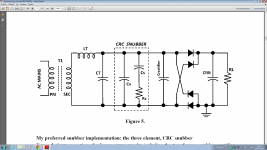
So 150nF + 100r form the zobel right ?
What sonic differences did you notice with this arrangement ? (In what equipment)?
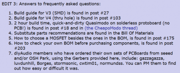
Post #1 in this thread includes Gerber files for PCB fabs, which you can send to board makers and have your own boards made. Quite a few DIYAudio members have had great success doing this, see item #7 below.
I've used OSHPark, seeed studio, itead studio, and DirtyPcbs to have PCBoards made. All of them built excellent boards at surprisingly low cost. And then you can give away or sell any extra boards that are left over after you build a few Quasimodos.
I've used OSHPark, seeed studio, itead studio, and DirtyPcbs to have PCBoards made. All of them built excellent boards at surprisingly low cost. And then you can give away or sell any extra boards that are left over after you build a few Quasimodos.
Attachments
stajo, try PM dsolodov here #468 http://www.diyaudio.com/forums/powe...-using-quasimodo-test-jig-47.html#post4080314.
Last year got his PCB V4 (thru-hole) package including PCB and all parts USPS First Class Mail US to Denmark and Paypal fee for $54,16. All parts have it's own little plastic bag with label (quality service 😀 and then can't go wrong assemble the kit).
Last year got his PCB V4 (thru-hole) package including PCB and all parts USPS First Class Mail US to Denmark and Paypal fee for $54,16. All parts have it's own little plastic bag with label (quality service 😀 and then can't go wrong assemble the kit).
Have Quasimodo V4 through hole version kits for sale in stock. The kit is 29USD with free shipping to the lower states. The kit is standard BOM. The boards are with ENIG finish. Parts are labeled and packaged in small plastic bags.
You have PM 🙂
The shipping to most European countries is $9.45 by USPS First Class International Mail vs $2.32 to the lower states in the United States. Please PM your e-mail for an invoice.Have Quasimodo V4 through hole version kits for sale in stock. The kit is 29USD with free shipping to the lower states. The kit is standard BOM. The boards are with ENIG finish. Parts are labeled and packaged in small plastic bags.
Okay, I've read through the relevant files, built it, did the math, thought about it, read over 500 posts about it (and I don't think I missed the explination), but still, I don't get it. Why a 4 switch DIP when a 2 switch would have done the same? Why have besides the all switch off 120Hz option, also the 600Hz, 2500Hz and 3000Hz options? If the 120Hz is suficient for anything I might want to do with this, then I will just leave the DIP switch out like it is now. So........... Mark, what were your original reason(s) why you included the DIP switches.
Attachments
Think about it for a while. If you'd rather not think, if you just want somebody to tell you the answer, it's there among the first 49 posts in the CheapoModo discussion thread.
{I've set up my DIYA profile to display 50 posts at a time, rather than the default 10 posts at a time}
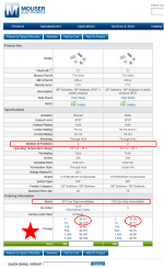
About DIP switches: I prefer the gold plated contact types. Here they are at Mouser Electronics (attached). Which of these would YOU use in a Quasimodo ThruHole board?
_
{I've set up my DIYA profile to display 50 posts at a time, rather than the default 10 posts at a time}
About DIP switches: I prefer the gold plated contact types. Here they are at Mouser Electronics (attached). Which of these would YOU use in a Quasimodo ThruHole board?
_
Attachments
Okay, thats part of the mystery solved, I'll sleep over the other half before looking.Which of these would YOU use in a Quasimodo ThruHole board? _

Have Quasimodo V4 through hole version kits for sale in stock. The kit is 29USD with free shipping to the lower states. The kit is standard BOM. The boards are with ENIG finish. Parts are labeled and packaged in small plastic bags.
I sent you a PM.
On the other hand, the probability of accidentally generating a runt pulse is increased by the frequency ratio, which you calculate to be (3000/120) = 25X. See post #267 for a scope photo.At 120hz the image on the scope is being refreshed at a rate of only 0.04 compared to the 3kHz.
Last edited:
- Home
- Amplifiers
- Power Supplies
- Simple, no-math transformer snubber using Quasimodo test-jig