twist the CT wire with the two secondary wires.
Yes, for each of two sets of secondaries per channel.
Take this twisted triplet to the rectifier.
This twisted triplets first goes to the barrier strip so that they may become a single twisted triplet. The snubbers are mounted there. Then this twisted triplet goes to the rectifier.
Pass the CT wire straight across the rectifier.
Yes.
Connect the two secondary wires to the rectifier.
Yes
Twist the CT wire with the two DC wires from the rectifier.
Yes
Take the twisted triplet to the smoothing capacitors.
At this point the twisted triplet goes to the first set of relays that provide the power-on delay. The twisted triplet cannot be intact, but is as close as possible.
It is here that the twisted triplet breaks apart.... the CT line goes to the board an the secondaries go on to the common terminals of the thermistor bypass relay.
I realize now, that the twisted triplet ought to go to the common terminals on the Form C relay that switches between thermistor and direct connection. It is with the direct connection that the CT line should continue.
Terminate the three wires on the first stage smoothing caps.
This can happen if the CT line continues to the thermistor bypass relay.
Keep the LOOPS at each end of the twisted triplets as small as possible.
To attach to the PS board, there are three contacts, quite far apart. Wiring can be routed to be flat to the boards and 180 degrees in direction, hence no loop.
This minimises loop area AND uses cancellation of fields in each wire to attenuate the emitted radiation even lower than close coupled triplet.
Thanks for the detailed explanation. I got confused at the thermistor bypass, as I originally was trying to get the CT line to go with the thermistor part as well as the bypass. This was not right. The CT line need only go with the bypass wiring, as that is what is in use when the amp is in use.
Yes, that is you analysing the Flow and Return routes.The CT line need only go with the bypass wiring, as that is what is in use when the amp is in use.
would a full-wave, center tapped secondary (one diode in series with each winding (two total) and the center tap connected to ground) be tested as "2 secondaries in series" in the documentation, and ultimately result in one C || C + R snubber (which never touches the center tap, just across the other two wires)?
In addition to this scenario, I am confused by scenario #5 in the documentation. The center-tap never really connects to the bridge, so why is it considered? The CT goes to a mid-point of two series capacitors that are placed across the output of the bridge. I would think like the question above, a single C || C + R snubber would work.
It is my understanding that for center tapped secondaries, there are to be two snubber circuits, one for each secondary. The ringing occurs between the CT and each secondary, not from secondary to secondary.
The documentation states that the snubber R and C values are to be obtained by connecting one secondary and CT to Quasimodo. The other secondary is to be shorted to the CT. The values obtained are to be used in two snubbers one for each coil.
The documentation states that the snubber R and C values are to be obtained by connecting one secondary and CT to Quasimodo. The other secondary is to be shorted to the CT. The values obtained are to be used in two snubbers one for each coil.
Luvdunhill, I would be glad to offer comments and suggestions about your analysis of the situation. You will be the one doing the work, performing the analysis. You will be the one drawing the schematics and running the simulations. I will be the one making single sentence remarks, and asking you follow-up questions in the Socratic tradition.
I see that you've posted messages to LTSPICE threads and transistor spice-modeling threads here on DIYA, which is great. SPICE is a convenient way to investigate snubbers, and LTSPICE is especially good because you get human readable schematics as part of the process. Glad you're already on the bandwagon.
I imagine it may take between four and twenty hours of your time, to do all the necessary work to gain a full, complete, and deep understanding of the situation. If you're not that interested, it isn't a problem. We can drop it.
Thanks Mark, already heading down that path 🙂 I will report back once I get stuck, thanks for the offer to be the gadfly!
Ok, now I'm ready to ask some better questions!
I've validated my QM works using the Inductor method and it was spot on.
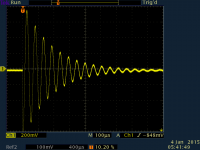
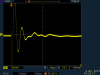
Here's my first result.
The first attachment is Cs = 150nF, Cx = 10nF, Rs = infinity.
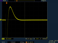
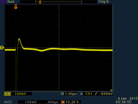
The second attachment is Cs = 150nF, Cx = 10nF, Rs = 577.
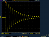
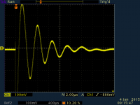
The third attachment is Cs = 150nF, Cx = 150nF, Rs = infinity.
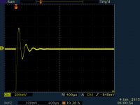
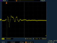
The fourth attachment is Cs = 150nF, Cx = 150nF, Rs = 327. In this case, it's impossible to find a zeta = 1.
This transformer is a Hammond 229C40. Both secondaries measure nearly identical.
I've validated my QM works using the Inductor method and it was spot on.
Here's my first result.
The first attachment is Cs = 150nF, Cx = 10nF, Rs = infinity.
The second attachment is Cs = 150nF, Cx = 10nF, Rs = 577.
The third attachment is Cs = 150nF, Cx = 150nF, Rs = infinity.
The fourth attachment is Cs = 150nF, Cx = 150nF, Rs = 327. In this case, it's impossible to find a zeta = 1.
This transformer is a Hammond 229C40. Both secondaries measure nearly identical.
Attachments
Last edited:
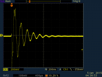
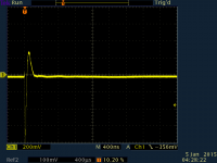
My second is a Hammond 160H12. I cannot get it to ring as nicely. I've tried both Cx = 10nF and Cx = 150nF, here's what I get:
The first attachment is Cs = 150nF, Cx = 10nF, Rs = infinity
The second attachment is Cs = 150nF, Cs = 10nF, Rs = 11.5. In this case, that's as close as I can get to zeta = 1.
The transformer is configured the same as the one above.
So, my question: why doesn't this one ring as clearly?
The first attachment is Cs = 150nF, Cx = 10nF, Rs = infinity
The second attachment is Cs = 150nF, Cs = 10nF, Rs = 11.5. In this case, that's as close as I can get to zeta = 1.
The transformer is configured the same as the one above.
So, my question: why doesn't this one ring as clearly?
Attachments
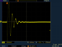
Oddly, if I remove the short on the second secondary, I get more wiggles and much more symmetric ring, see attached. It's really hard to get zeta = 1, the trim pot is nearly at the bottom of it's adjustment range and it ends up looking more like zeta = 2 or zeta = 3...
Attachments
Last edited:
I decided to play a bit more. First I tried to vary the input voltage to the QM. Second, I decided to go lower in capacitance values. Here's what I got:
First plot is Cs = 100nF, Cx = 1nF, Rs = infinite
Second plot is Cs = 100nF, Cx = 1nF, Rs = 33.2
Third plot is Cs = 100nF, Cx = 220pF, Rs = infinite
Fourth plot is Cs = 100nF, Cx = 220pF, Rs = 25.1
Fifth is Cs = 100nF, Cx = 33nF, Rs = infinite
First plot is Cs = 100nF, Cx = 1nF, Rs = infinite
Second plot is Cs = 100nF, Cx = 1nF, Rs = 33.2
Third plot is Cs = 100nF, Cx = 220pF, Rs = infinite
Fourth plot is Cs = 100nF, Cx = 220pF, Rs = 25.1
Fifth is Cs = 100nF, Cx = 33nF, Rs = infinite
Attachments

Perhaps something else to add to the 'test list' is to re-connect the transformer into a known piece of equipment and see how the snubber/no snubber sound varies and how it can improve a simple C-R-C power supply, for example.
My second is a Hammond 160H12. I cannot get it to ring as nicely. I've tried both Cx = 10nF and Cx = 150nF, here's what I get:
The first attachment is Cs = 150nF, Cx = 10nF, Rs = infinity
The second attachment is Cs = 150nF, Cs = 10nF, Rs = 11.5. In this case, that's as close as I can get to zeta = 1.
The transformer is configured the same as the one above.
So, my question: why doesn't this one ring as clearly?
I also found that shorting all the spare windings resulted in a "too small" voltage at the test winding to make much sense of any readings I was getting.Oddly, if I remove the short on the second secondary, I get more wiggles and much more symmetric ring, see attached. It's really hard to get zeta = 1, the trim pot is nearly at the bottom of it's adjustment range and it ends up looking more like zeta = 2 or zeta = 3...
With a lot of adjustment I was able to find the best resistor value.
It turned out that using a 1channel input to the scope was my mistake.
I have not repeated the testing using both channels of the scope.
- Cs = 150nF, Cx = 10nF
- Cs = 150nF, Cx = 150nF
- and others
If you really know what you're doing, use whatever values of Cx and Cs you wish.
If you don't really know what you're doing, I suggest you set your capacitor ratio (Cs / Cx) to a value that conforms with the guidelines & recommendations in the Quasimodo design note. Cs and Cx are related; you only have the freedom to choose one of them. Once you pick it, the (Cs / Cx) ratio dictates the other.
I also suggest you estimate the capacitance of the rectifiers you plan to use with your transformer. The design note recommends that you select (Cx >> Crectifier) and if you don't really know what you're doing, I suggest you follow this recommendation. If you really do know what you're doing, feel free to frolic around, however you like.
Here's an example that I copied from the Cordell Audio website. It is a SPICE model of a 1000V, 35 ampere diode ... one of the four diodes in a GBPC3502 bridge rectifier assembly:
.model BRIDGE35A D(Is=20000n Rs=.006 N=2.4 EG=1.3 XTI=.5 BV=200
+ IBV=1e-05 Cjo=500p Vj=1.3 M=.45 tt=4u Iave=4 Vpk=200 mfg=Cordell)
+ IBV=1e-05 Cjo=500p Vj=1.3 M=.45 tt=4u Iave=4 Vpk=200 mfg=Cordell)
Notice the parameter "Cjo=500p" -- that's the rectifier's capacitance at zero reverse bias: 500 picofarads. If you plan to use this diode bridge with your transformer, your Crectifier is 2X to 4X times 500pF. Crectifier appears in parallel with any snubber Cx that you might install. If you set Cx >> Crectifier as the Design Note recommends, then you can completely forget about Crectifier. Cx swamps it out.
Mark: Thanks! Given the data I gave in posts #528-#530, what would you recommend as snubber configuration for this transformer?
I tried a few larger transformers after I posted the above and quickly found good values. This one seems to escape me, but wanting to learn.
Andrew: I did play a lot with trigger using a single scope channel, despite what the screen captures lead you to think. I will try with a second probe, we will see if it helps.
Transformers with 115VAC primaries and 6.3VAC secondaries do tend to have quite low secondary leakage inductance. This means you need to be scrupulously careful to short the unused windings with low resistance. Don't use twelve inch long, 24AWG, alligator-clip jumper wires from Radio Shack! Instead, tack-solder the transformer wires to either end of a 1 inch long piece of solid copper wire and wrap with tape to insulate. You can unsolder after the measurement is complete.
Make sure your connections are correct; avoid garbage-in, garbage-out. Diagrams below.
You may find it beneficial to use a 200 ohm trimmer (example1) or a 100 ohm trimmer (example2) in your Quasimodo test jig, instead of the stock 1Kohm trimmer. These will give you finer granularity of control, in the low-ohms region where 6.3VAC transformers often operate.
Start by choosing two or three candidate rectifier diodes. Find the capacitance of each, and let the symbol "Crectifier" represent the LARGEST capacitance among your candidates. So if your three diodes are 30pF, 250pF, and 170pF, then "Crectifier" equals 250pF.
Choose Cx to be at least 2X greater than Crectifier. (5X is safer, and 200X is even safer).
Now that Cx is known, Cs is also known. Since the (Cs / Cx) ratio is fixed and frozen.
Plug the trimmer, your Cx, and your Cs into Quasimodo. Use a two channel scope, connect channel 1 to node DRAIN and channel 2 to node SCOPE. Trigger on channel 1, falling edge. Twirl the trimpot until the oscillations just barely go flat. Voila, done!
If you are still unable to get useful readings, you could ask someone else to do the measurements for you. You could send your transformer to another DIYaudio hobbyist and ask them to measure it for you. You of course will pay the shipping both ways.
_
Attachments
Last edited:
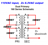
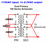
There is a reason why the figures are labeled 115VAC input.
A dual primary transformer such as the Hammond 160H12 can be configured for either 115VAC input or 230VAC input. Only one of those two configurations is shown in the figures attached to post 536. This is also the configuration shown in the Quasimodo design note, Figure 13(d) on page 11. Take a moment to count the number of shorts in the primary circuit of Fig. 13(d).
A dual primary transformer such as the Hammond 160H12 can be configured for either 115VAC input or 230VAC input. Only one of those two configurations is shown in the figures attached to post 536. This is also the configuration shown in the Quasimodo design note, Figure 13(d) on page 11. Take a moment to count the number of shorts in the primary circuit of Fig. 13(d).
I find it useful to restate this question slightly:Do the two shorted primaries need to be connected together?
Suppose Elmo The Experimenter connected a real Quasimodo to a real dual-primary, dual-secondary transformer. Suppose he captured the oscilloscope waveforms when (a) the primaries are shorted but not connected together; (b) the primaries are shorted AND connected together. Would the two captured oscilloscope waveforms be identical? Would they be wildly different? Would they be mostly similar but slightly different?
The restatement makes it clear that anybody who is sufficiently interested / motivated / curious, can answer the question.
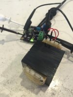
Transformers with 115VAC primaries and 6.3VAC secondaries do tend to have quite low secondary leakage inductance. This means you need to be scrupulously careful to short the unused windings with low resistance. Don't use twelve inch long, 24AWG, alligator-clip jumper wires from Radio Shack! Instead, tack-solder the transformer wires to either end of a 1 inch long piece of solid copper wire and wrap with tape to insulate. You can unsolder after the measurement is complete.
check. see first attachment.
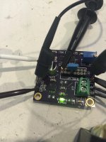
Make sure your connections are correct; avoid garbage-in, garbage-out. Diagrams below.
check. see second attachment. I have replaced the stock 150nF capacitor with Rs = 100nF. The capacitor in the socket is 10nF - Cx.
You may find it beneficial to use a 200 ohm trimmer (example1) or a 100 ohm trimmer (example2) in your Quasimodo test jig, instead of the stock 1Kohm trimmer. These will give you finer granularity of control, in the low-ohms region where 6.3VAC transformers often operate.
I used a 500 ohm.
Start by choosing two or three candidate rectifier diodes. Find the capacitance of each, and let the symbol "Crectifier" represent the LARGEST capacitance among your candidates. So if your three diodes are 30pF, 250pF, and 170pF, then "Crectifier" equals 250pF.
I chose CDBHD240-G, which has Cj = 150pF according to its datasheet.
Choose Cx to be at least 2X greater than Crectifier. (5X is safer, and 200X is even safer).
ok, 10nF
Now that Cx is known, Cs is also known. Since the (Cs / Cx) ratio is fixed and frozen.
ok, 100nF
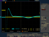
Plug the trimmer, your Cx, and your Cs into Quasimodo. Use a two channel scope, connect channel 1 to node DRAIN and channel 2 to node SCOPE. Trigger on channel 1, falling edge. Twirl the trimpot until the oscillations just barely go flat. Voila, done!
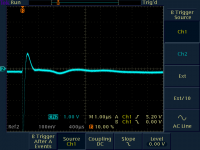
Ok, I believe I've done this. See next two attachments from the scope. I believe I have the Ch1 trigger working.
AndrewT: this didn't change the waveform at all, compared to just triggering using the same channel as the output waveform, per the docs.
This results in Rs = 12.5 ohms. I need to calculate the power through this resistor next.
Attachments
I assumed a SINE(0 8.9 60) source, Cx = 10nF, Cs = 100nF, Rs = 12.5 and get ~230uA RMS (+/-329uA) across Rs (I cannot seem to directly calculate power with LTSpice, I cannot get the thermometer icon), so I assume that's .23*.23*12.5 = 0.66mW (never really done much with AC power)
- Home
- Amplifiers
- Power Supplies
- Simple, no-math transformer snubber using Quasimodo test-jig