OK so I have borrowed a scope from dazed2. Any transformer we ring out behaves very well with a dead short as RS
Update.... replaced 4.7K resistor as extracting it to measure it separated the end caps.... maybe it was bad?
Now, we are getting dampening of four very different transformers at low levels. eg. 2 piece 1.4KVA 39 VAC toriods with independent secondaries wants to see 5.5-6 ohms with std BOM parts, a 37 VCT 185 VA toroid wants to see 10 ohms, and a 12 V, 12 VA with parallel dual secondaries wants to see 33 ohms.
Now, we are getting dampening of four very different transformers at low levels. eg. 2 piece 1.4KVA 39 VAC toriods with independent secondaries wants to see 5.5-6 ohms with std BOM parts, a 37 VCT 185 VA toroid wants to see 10 ohms, and a 12 V, 12 VA with parallel dual secondaries wants to see 33 ohms.
Congratulations!
If you feel like doing some math, you can calculate Ls from the ringing frequency at Rsnub=infinity. Then once you know Ls you can calculate Rsnub which mathematically should give Zeta=1.0, when paired with the Cx value you have selected.
Does your calculated Rsnub, agree with your quasimodo "this Rsnub gives damped waveforms that look good to my eyeball" value? If so, consider it to be CONFIRMED. And you used mathematics! You've earned your merit badge in studliness.
Congratulations!
If you feel like doing some math, you can calculate Ls from the ringing frequency at Rsnub=infinity. Then once you know Ls you can calculate Rsnub which mathematically should give Zeta=1.0, when paired with the Cx value you have selected.
Does your calculated Rsnub, agree with your quasimodo "this Rsnub gives damped waveforms that look good to my eyeball" value? If so, consider it to be CONFIRMED. And you used mathematics! You've earned your merit badge in studliness.
OK, will do this a report back.
OK, will do this a report back.
Hello BigE,
If you perform the calculations as Mark suggested, you might consider cross-checking the results obtained by using the attached Excel sheet (the first version of it was posted earlier in this thread, s. post #451).
If you enter 1.0 for the optimum damping value into cell G3, the ringing frequency you measured into cell E15, and the secondary winding resistance into D15, then you should obtain the inductance in cell F15 and the snubbing resistance in cell J15.
If your Cx value is not 10nF, enter your value into cell C3.
Regards
Braca
Attachments
People who've built themselves a Quasimodo test-jig have been asking, "How can I test this thing and assure myself that it's working properly?"
One straightforward way to qualify & certify your test-jig, is to recall that
We can use Quasimodo to measure a known inductor, and see whether the Quasimodo measurement of inductance agrees with the known correct answer. If it does then we are confident that Quasimodo is working, and more importantly, producing the right answer.
Equations (A.10) and (A.11) in the Quasimodo design note, present the relationships. The Greek letter "lowercase omega sub n" (looks like a funny "w") is angular frequency in radians per second. Some Audio people are more comfortable with cycles per second (also called Hertz); to convert back and forth,
To assist readers who find equations and Greek letters a little daunting, I've made a table of worked examples including the correct answers, below. Try two or three of these yourself, to make sure you're punching the buttons on your calculator correctly. Be sure that when you plug these values into equations (A.10) and (A.11), the answer that pops out of your calculator agrees with the answer in the table. Then you're good to go: plug in YOUR values from YOUR inductor experiment and punch the calculator keys the same way.
(You could also use it as a lookup table, which avoids equations and calculators entirely. But that would be lazy and nobody who builds a Quasimodo is lazy!)
You may notice a couple of repeating patterns in the table of numbers below. That's not a surprise or a coincidence, that's just plain old math.
_
One straightforward way to qualify & certify your test-jig, is to recall that
... Quasimodo is simply a machine which measures inductance.
We can use Quasimodo to measure a known inductor, and see whether the Quasimodo measurement of inductance agrees with the known correct answer. If it does then we are confident that Quasimodo is working, and more importantly, producing the right answer.
Equations (A.10) and (A.11) in the Quasimodo design note, present the relationships. The Greek letter "lowercase omega sub n" (looks like a funny "w") is angular frequency in radians per second. Some Audio people are more comfortable with cycles per second (also called Hertz); to convert back and forth,
- omega = 2 * Pi * f
- f = omega / (2 * Pi)
STEP 1. Obtain an inductor whose inductance is known within 5%. DigiKey will sell you many hundreds of 5% inductors for less than USD 0.50 apiece (link).
STEP 2. Attach the inductor to your Quasimodo test jig, select Cx and Cs, and remove the trimpot from its socket (i.e. set Rsnub = infinity). Measure the ringing frequency.
STEP 3. Return the trimpot to its socket, and while watching the oscilloscope trace, dial the trimpot to get a well damped waveform (zeta=1). Measure the Rsnub which gives the zeta=1 waveform.
STEP 4. Apply equations (A.10) and (A.11) {or their daughters in post 257 of this thread} with the known inductance, to calculate the mathematically predicted ringing frequency and the mathematically predicted Rsnub value.
STEP 5. Was the predicted frequency pretty close to the measured frequency? Was the predicted Rsnub pretty close to the measured Rsnub? If so then your Quasimodo test-jig is working fine. If not then you've got some debugging to do.
To assist readers who find equations and Greek letters a little daunting, I've made a table of worked examples including the correct answers, below. Try two or three of these yourself, to make sure you're punching the buttons on your calculator correctly. Be sure that when you plug these values into equations (A.10) and (A.11), the answer that pops out of your calculator agrees with the answer in the table. Then you're good to go: plug in YOUR values from YOUR inductor experiment and punch the calculator keys the same way.
(You could also use it as a lookup table, which avoids equations and calculators entirely. But that would be lazy and nobody who builds a Quasimodo is lazy!)
You may notice a couple of repeating patterns in the table of numbers below. That's not a surprise or a coincidence, that's just plain old math.
_
Attachments
Thanks Mark!
I have a question though, about #3. I don't know what to look for to see zeta=1 when viewing the chart.
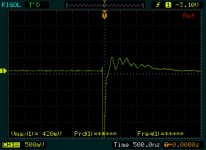
I used a 4.5mH inductor (Erse super-Q) for this test. And I was able to reproduce your numbers in a spreadsheet, so I calculated the value for the 4.5mH inductor. The scope gave me the ringing frequency ( fosc ) = 25KHz.
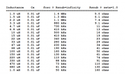
I took four snapshots. The first is the ringing. Note the scale and the frequency. Note also that the scale is 50mv for shots 2,3 and 4.
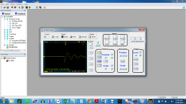
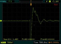
The second is at the calculated Rsnub for zeta = 1, being Rs=353.43 ohms
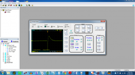
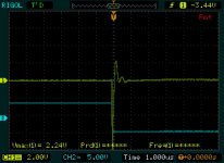
The third shows Rs= 246 ohms
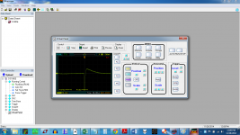
The fourth shows Rs =149 ohms
Why would we not choose one of these lower values?
I have a question though, about #3. I don't know what to look for to see zeta=1 when viewing the chart.
I used a 4.5mH inductor (Erse super-Q) for this test. And I was able to reproduce your numbers in a spreadsheet, so I calculated the value for the 4.5mH inductor. The scope gave me the ringing frequency ( fosc ) = 25KHz.
I took four snapshots. The first is the ringing. Note the scale and the frequency. Note also that the scale is 50mv for shots 2,3 and 4.
The second is at the calculated Rsnub for zeta = 1, being Rs=353.43 ohms
The third shows Rs= 246 ohms
The fourth shows Rs =149 ohms
Why would we not choose one of these lower values?
Attachments
Last edited:
I'm new to this and might well be wrong but.... look at the waveform and how long it takes to return to normality. The two on the right are over-damped/unresponsive.
From Mark's writeup, in appendix A:
"Our goal is to choose the snubbing resistor R such that Zeta > 1, ie to overdamp the system. This goal is met when 2R < Sqrt( 1/(L*(Cx+Ct))) "
The resistor values calculated in the table are for Zeta = 1. That is critical damping.
Which is why I was confused about step 3. If we are looking for overdamping, *many* values of R will satisfy.
If you really know what you're doing, choose any Zeta you like. If you don't really know what you're doing, I recommend you stick with Zeta=1.0. It's the most forgiving choice with the greatest margin of safety both above and below. If there's a chance you've connected your scope wrong, or read the potentiometer resistance wrong, or interpreted the scope waveform incorrectly, you really do want to be aiming at Zeta=1.0.
If, through error or bad luck, you miss the bulls-eye, at least you'll hit the target.
(Post #263 in this thread) has more to say about this topic.
If, through error or bad luck, you miss the bulls-eye, at least you'll hit the target.
(Post #263 in this thread) has more to say about this topic.
I've read Hagermann, and he suggests zeta=0.5 so that the resistor does not need to be so high powered (relatively speaking). Problem is, I would not know how to identify 0.5 with certainty just by looking at the screen.
But it is comforting to know that if there is a little wiggle in it, that the world won't end.
But it is comforting to know that if there is a little wiggle in it, that the world won't end.
It appears that you successfully calculated (Rsnub which gives zeta=1.0), installed that resistor into Quasimodo, and then took a picture of the resulting waveform {post #488}.
Why don't you calculate (Rsnub which gives zeta=0.5), install it into Quasimodo, and take a picture of that waveform? You might really hate it / or you might really like it. Why not capture the zeta=0.5 waveform, study it a while, and see how you react?
Why don't you calculate (Rsnub which gives zeta=0.5), install it into Quasimodo, and take a picture of that waveform? You might really hate it / or you might really like it. Why not capture the zeta=0.5 waveform, study it a while, and see how you react?
At some point I should read Mark's paper again. At one point Mark pointed me to the logarithmic decrement method of extracting the damping factor in an observed waveform. As I was doing some reading in this regard, I came across this website discussing second order linear systems, their impulse and step responses and damping factors etc.
The mathematics more than strained my recollection of high school calculus but it's interesting to observe their interactive graphics/movies, specifically comparing the zeta with the shape of the waveform. If, as I seem to recall Mark recommending in his example, one damps the circuit just enough to bring the bottom of the second wave up to zero then the achieved zeta is more like 0.65.
I'm sure Mark will remind that I have omitted to factor in a, b and c (at least)...😱
If you really know what you're doing, use any zeta you like.
On the other hand if you don't really know what you're doing, I recommend using zeta = 1.0. It is more forgiving of the types of misunderstandings and mistakes that people often make.
It is of course possible to cross check your hand calculations against SPICE simulations, perhaps using the LTSPICE schematic and .asc file found in the Cheapomodo thread. When the two agree, it boosts your confidence in each one. You could plot the transient response for several different zeta values (like Figure 1 of the Quasimodo design note) and see how your personal choice of zeta stacks up against other possibilities.
If you really know what you're doing, you can devise a way to use a Quasimodo to measure the damping factor zeta of your transformer arrangement with no snubber whatsoever (not even a Cx). Thanks to hysteresis losses in the core and copper resistive losses in the secondary winding, zeta won't be zero. But how close to zero is it? Maybe you're happy with the totally-unsnubbed zeta, and can save board area & parts cost by eliminating the snubber? Plenty of well-loved high end audio products don't have a snubber, maybe your DIY project can join them.
Well, count me as one of those that does not know what he is doing!
My implementation is not quite straightforward either. I am using two secondaries in parallel, but they are center tapped.
I rang out the transfomer shorting all but one secondary/CT winding. I tested each one just to make sure.
I plan to put in the snubber circuits in parallel as well. In fact, as the two sets of secondaries are being joined at a barrier strip, it is on this barrier strip that I will be putting *both* snubber circuits.
Is there any problem with this approach?
Thanks!
Hmmm seems to be less than perfect.
The shots are of three implementation of snubbing. The second shot is quasimodo dealing with the parallel secondaries with the snubber designed for a single secondary.
The third shot was taken after a second snubber was added. Rs=15, Cs=150nf, Cx=10
The first is using Quasimodo on the paraellel secondaries.
Here, quasimodo says go with 1/2 of the Rs value for a single CT/secondary winding. So, that is what I shall do... This is being treated like the parallel secondary case, and quasimodo is ringing out both.
Attachments

would a full-wave, center tapped secondary (one diode in series with each winding (two total) and the center tap connected to ground) be tested as "2 secondaries in series" in the documentation, and ultimately result in one C || C + R snubber (which never touches the center tap, just across the other two wires)?
- Home
- Amplifiers
- Power Supplies
- Simple, no-math transformer snubber using Quasimodo test-jig