Braca, it may be worthwhile rounding off some of those result columns ;-)
Thanks for the suggestion; it does make sense & will be included in the next release.
regards,
Braca
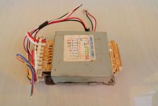
Here is mine
using EL Trannies, using part that i already have
Cx = 10nF, Cs = 220nF and Rs = 5K pot parallel with 2K2
Rs about 45 Ohm
Thank you for the data, but I must say that I have mixed feelings about including this transformer into the table. It is a device with three different centre-tapped secondaries, and it would be very interesting to see what Rs values would be obtained by ringing each of them separately (I don't remember having seen a transformer like this in this thread).
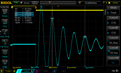
As it is I could enter the results for the single secondary (I guess it is one of the two with the lower voltages), and then only thanks to the scope screenshot you attached, from which I can visually estimate a ringing frequency of about 270kHz. I'd rather had a measured value that I asked for in my previous post; and having produced this screenshot you were only a few simple steps away from actually measuring the ringing frequency. I'm sure your scope has cursors, and if you look at the screenshot below that illustrates the method, you only have to position them two or more peaks or valleys from each other, read off the time difference between them, and calculate the frequency. In the example below, the cursors are three periods away from each other, so the ringing frequency is three times higher than the value 1/[dX]=11.57kHz displayed, i.e. 3*11.57=34.7kHz.
Returning to your results, with the ringing frequency of 270kHz the theory predicts Rs=42 Ohm for Zeta=0.707, which checks with the value you obtained experimentally. Well done!
If you're handy with Excel or another worksheet software, you can enter the data into your local copy of the table and have a look at the results yourself.
So if you feel like measuring the other two secondaries as well I would be glad to include them into the table.
Regards,
Braca
P.S. I'm not publishing the table now in order not to overload the thread; I'll be happy to do it each time a couple of new entries have been made available.
Attachments
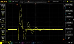
I measured six 625VAC power transformers made by 3 different manufacturers yesterday. I shorted the primary and one of the secondaries then measured the other secondary. The capacitors across the secondaries are 10nF. The snubbing capacitors are 100nF.
LCR meter showed leakage inductance ranging from about 10uH to 30uH for the six transformers.
The Quasimodo test-jig showed good damping achieved with resistors from about 14R to 20R. I am not 100% certain if the test-jig's circuit is equal to the full wave rectification from single diode bridge with 2 transformer secondaries / centre tap ground.
I calculated the resistor value using the original Jim Haggerman formulas, and got the resistor values from about 30R to 50R.
I plotted the Jim Haggerman's circuit in LTSpice. The resistor values were found to provide good damping from 15R to 30R, depending on the leakage inductance. It appears 24R should work fairly well for all 6 transformers.
I guess that the resistor value is really not that critical. I am thinking about using 24R for all of my 625VAC transformers.
What do you think?
Last edited:
Note that R = sqrt(L/C). After the sqrt() function, the R changes less than L or C. So even though the leakage inductance is between 10uH and 30uH, the R range is smaller. Using any resistor value, the ringing can be seen substantially reduced comparing to without RC damping.
The use of the 10nF already reduces the ringing frequency to about 200kHz to 500kHz. There is absolutely no problem getting rid of the noise with any approximate R value in the snubber in a power supply using CRCRC.
The use of the 10nF already reduces the ringing frequency to about 200kHz to 500kHz. There is absolutely no problem getting rid of the noise with any approximate R value in the snubber in a power supply using CRCRC.
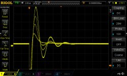
crt, that overlaid scope display is beautiful! Congratulations.
Thank you for releasing this circuit 🙂
i usually copying other snubber value, without knowing what i'm doing 😱
Thank you for the data, but I must say that I have mixed feelings about including this transformer into the table. It is a device with three different centre-tapped secondaries, and it would be very interesting to see what Rs values would be obtained by ringing each of them separately (I don't remember having seen a transformer like this in this thread).
As it is I could enter the results for the single secondary (I guess it is one of the two with the lower voltages), and then only thanks to the scope screenshot you attached, from which I can visually estimate a ringing frequency of about 270kHz. I'd rather had a measured value that I asked for in my previous post; and having produced this screenshot you were only a few simple steps away from actually measuring the ringing frequency. I'm sure your scope has cursors, and if you look at the screenshot below that illustrates the method, you only have to position them two or more peaks or valleys from each other, read off the time difference between them, and calculate the frequency. In the example below, the cursors are three periods away from each other, so the ringing frequency is three times higher than the value 1/[dX]=11.57kHz displayed, i.e. 3*11.57=34.7kHz.
Returning to your results, with the ringing frequency of 270kHz the theory predicts Rs=42 Ohm for Zeta=0.707, which checks with the value you obtained experimentally. Well done!
If you're handy with Excel or another worksheet software, you can enter the data into your local copy of the table and have a look at the results yourself.
So if you feel like measuring the other two secondaries as well I would be glad to include them into the table.
Regards,
Braca
P.S. I'm not publishing the table now in order not to overload the thread; I'll be happy to do it each time a couple of new entries have been made available.
You don't have to put it on list, seller of this transformer says this trannies a surplus parts from Sony/Panasonic equipment and i believe the population on martket is very small
Thanks for your explanation, i'm still trying to "understand" what are you wrote. Since my math is no good
Actually i had measure for 14-CT-14 too and got smaller Rs about 21 Ohm, but not measure 3-0-3 since i'm not using it.
Attachments
Last edited:
I have a small variety of such transformers. Leads one to think about building a Class-A/G amplifier, but the transformers themselves are often only capable of somewhat limited VA.
Note that R = sqrt(L/C).
Actually, R = (0.5/zeta)*sqrt(L/C)
If you omit the factor of (0.5/zeta) then the calculated R gives you an underdamped response, which I do not recommend for people that don't know what they're doing. On the other hand, for people who DO know what they're doing, I cheerfully encourage you to use whatever damping your engineering intuition suggests. I myself prefer critically damped (zeta=1).
When adjusting the R while watching a scope, there is a nice broad region surrounding zeta=1 where the waveforms are smooth and acceptable. Especially if you use a 20-turn trimmer, you can twirl that baby quite a lot and still have a very pleasant scope trace. Reassuringly, it is not fussy. If you like the waveforms you get with zeta=0.8, nobody can stop you from using that. Same is true if you like zeta=1.3. The good news is, with your own eyes you can see the ringing become damped to exactly the waveshape that YOU like. You know exactly what you're getting.
Remember this is not a 100kHz switchmode power supply; at mains frequency where these snubbers operate, we have the freedom to smear the diode switch-off transient across hundreds and hundreds of microseconds if we see fit.
Thanks, Mark.
With 770 posts it is hard to go back and find the post with the recommended optimal (zeta=1) curve. Do you know which post has it? I would like to see that graph again.
With 770 posts it is hard to go back and find the post with the recommended optimal (zeta=1) curve. Do you know which post has it? I would like to see that graph again.
Note that R = sqrt(L/C). After the sqrt() function, the R changes less than L or C. So even though the leakage inductance is between 10uH and 30uH, the R range is smaller. Using any resistor value, the ringing can be seen substantially reduced comparing to without RC damping.
The use of the 10nF already reduces the ringing frequency to about 200kHz to 500kHz. There is absolutely no problem getting rid of the noise with any approximate R value in the snubber in a power supply using CRCRC.
It appears that your inductance and natural frequency data are not quite consistent, since if the inductance range is 1:3, then the natural frequency range with the same 10nF capacitor must be 1/sqrt(3).
Assuming that your inductance values are correct, the 24R resistor that you would like to apply to all six transformers would result in Zeta=1.15 with L=30uH, and Zeta=0.67 wit L=10uH. The latter case is a bit underdamped, but my experience with checking the snubber performance in several running power supplies indicates that also in such cases the ringing is sufficiently damped.
Regards,
Braca
To see a critically damped response (zeta=1.0), look at the first figure of the first post (#1) in this thread on diyAudio. Do you see a red curve labeled "109R" ? Do you see text in the body of the post which call this "critical damping" ?
A zoomed-in picture of a critically damped response (zeta=1.0) is also shown in Figure 1 of the Quasimodo design note. The design note is a PDF document which is attached to post#1 of this thread. View post#1 and scroll down to the last few items in it. You will see "Attached Files". Bingo.
I'm curious: did it occur to you, to look at the first post?
Thanks, gentlemen.
Braca, you are correct. Referring to Mark's graphs, zeta between 0.5 and 1.3 was what I got. I was quite happy with zeta between 0.5 to 1.3 or so by looking at the waves. The noise difference is so minimal in the frequency region that my CRLCRLCRLC supply has a theoretical 130dB noise rejection. I suppose I could use the optimal zeta=1 for each secondary, but when you are upgrading 4 stereo 8 channel mono-blocks 16 snubbers you may want to keep it simple.
Mark, I did read the first post initially and downloaded your PDF document. I didn't do it the last time - I know I am getting old.
Last edited:
Before I put a Seeed order in, anyone got a spare board they'd be willing to send to UK? If so, please PM me.
Before I put a Seeed order in, anyone got a spare board they'd be willing to send to UK? If so, please PM me.
Sorted. Thanks cwtim01.
My tranny
Sooo, can someone have a look please?
I did my own Quasimodo ExtraLight experiment.
R-core transformer is a Toroidy Audio grade 400VA 2x18V. All leads are open, only one secondary attached to a square wave generator at 110Hz or so.
R1 = 10kOhm, Cx = 10nF, Cs = 150nF
Scope traces for different Rs are attached. I find the lowest amplitude of the ringing with Rs = 304 Ohm. But I can't quench it.
Is this expected? Shall I change anything?
I also attach two traces, one without any snubber element, and one with only Cx. The difference seems only to be in much lower noise.
Edit: traces are 0.2ms/div and 50mV/div, approx.
Attachments
Last edited:
Unfortunately that's not the correct way to connect Quasimodo (or its ExtraLight progeny) to a transformer for oscillatory ringing tests.R-core transformer is a Toroidy Audio grade 400VA 2x18V. All leads are open, only one secondary attached to a square wave generator at 110Hz or so. R1 = 10kOhm, Cx = 10nF, Cs = 150nF
Please see Figures 2 and 13 of the Quasimodo design note, a .pdf file attached to post#1 of this thread. Carefully notice the bold black shorting bar(s) in Fig.13.
- Home
- Amplifiers
- Power Supplies
- Simple, no-math transformer snubber using Quasimodo test-jig