Hi. Braca. If you were keen, it would be great to see a waveform with the very commonly used UF400x, as a benchmark.
Hi. Braca. If you were keen, it would be great to see a waveform with the very commonly used UF400x, as a benchmark.
Hello trobbins, I take your point re. benchmark. Unfortunately, I have no UF400x diodes at the moment, and my next parts order will be in a week's time.
On the other hand, UF400x rank among the best in Mark's survey. My goal was to test the worst offenders, i.e. the ones producing the strongest ringing.
Regards,
Braca
UF400x rank among the best in Mark's table in Linear Audio
7th out of 48 @ 100mA constant current load. Percentile ranking: top 14.5%
Not measured @ 2.0A constant current load (diode max rating < 2A)
In an effort to shrink this PCB, I purchased a couple of "AVB" transformers from the German manufacturer called Block. (Here is their sales page.)
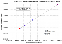
To my great surprise, I found that the secondary leakage inductance of these tiny transformers was almost four Henrys (!). I used the linear regression method to measure this inductance; it is discussed in the Quasimodo Design Note {attached to post #1 of this thread}, Appendix C.
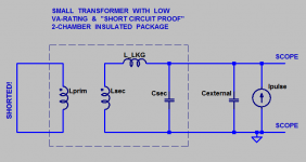
We short out the primary which effectively shorts out the secondary, leaving only the Leakage inductance active. Then we apply a current pulse and measure the frequency of oscillation. We do this for several different values of Cexternal, and then use linear regression to extract the Leakage inductance "L_LKG" and the secondary capacitance "Csec".
Shown below are my measurements. The extracted leakage inductance was 3.805 Henrys [call it 3.8] and the extracted secondary capacitance was 87.31 pF [call it 90].
Here's an amusing result: if we connect this transformer to a PCB and rectifiers whose total capacitance adds up to 150 pF more, then the optimal value of snubber resistance which gives perfect zeta=1.00 damping, is
Self identified Circuit Theorists may enjoy this thought exercise: ask yourself what would happen if you fitted a 39K resistor instead of a 63K resistor (to a 30VRMS transformer)? Is 39K better, worse, or equally good?
_
To my great surprise, I found that the secondary leakage inductance of these tiny transformers was almost four Henrys (!). I used the linear regression method to measure this inductance; it is discussed in the Quasimodo Design Note {attached to post #1 of this thread}, Appendix C.
We short out the primary which effectively shorts out the secondary, leaving only the Leakage inductance active. Then we apply a current pulse and measure the frequency of oscillation. We do this for several different values of Cexternal, and then use linear regression to extract the Leakage inductance "L_LKG" and the secondary capacitance "Csec".
Shown below are my measurements. The extracted leakage inductance was 3.805 Henrys [call it 3.8] and the extracted secondary capacitance was 87.31 pF [call it 90].
Here's an amusing result: if we connect this transformer to a PCB and rectifiers whose total capacitance adds up to 150 pF more, then the optimal value of snubber resistance which gives perfect zeta=1.00 damping, is
- Rdamp = (1/2) * sqrt(3.8 / (9E-11 + 1.5E-10)) = 62,900 ohms
Self identified Circuit Theorists may enjoy this thought exercise: ask yourself what would happen if you fitted a 39K resistor instead of a 63K resistor (to a 30VRMS transformer)? Is 39K better, worse, or equally good?
_
Attachments
Last edited:
Funny, it was only yesterday that I was about to use Quasimodo on a just delivered Block VC5.0/1/6 transformer (2x6V/5VA) only to find out that it was DOA. They are sending me the replacement now, but it will take three days to reach me.
Meanwhile, and to second the question of AndrewT, would it be possible to also post a scope screenshot of the AVB transformer ringing with Cx=10nF?
Regards,
Braca
Meanwhile, and to second the question of AndrewT, would it be possible to also post a scope screenshot of the AVB transformer ringing with Cx=10nF?
Regards,
Braca
Meanwhile, and to second the question of AndrewT, would it be possible to also post a scope screenshot of the AVB transformer ringing with Cx=10nF?
Regards,
Braca
I believe Mark's point is that no Cx or Cs is needed.
Mark,
I have never looked at short circuit proof transformers.
I notice that regulation for a 2x6Vac 3.2VA is 57%. They quote a 1.57x factor.
That is quite a bit higher than any 5 to 6VA transformer I have bought. They are around 30% regulation.
Lots of very thin wire giving lots of emf combined with highish winding resistance.
Is this a clue to it's short circuit proof capability?
Hmmm, I purchased 8 of them but only tested three. I'll write myself a little reminder note to see if any of the others are obviously dead or severely wounded, next time I'm fooling around with itty bitty transformers. It would be rather disappointing if the failure rate @ receiving desk was above 0.1%.
I imagine that Block achieves "short circuit proof" transformers by having excellent insulation and TRULY excellent testing of insulation. I also imagine they deliberately use very thin wire, thin enough to act as a fuse. (I made up the following numbers myself, these are wild guesses) I imagine the primary wire is thin enough that it fuses/melts/open-circuits if it carries >3X the max rated primary current for >30 seconds. Same for the secondary wires. Maybe they even install a short piece of actual fuse material, between each external pin and its internal terminal.
I also suspect they use some kind of electrically nonconductive material for the transformer core. Maybe compressed ferrite powder in a nonconductive binder matrix, or perhaps hi-mu steel alloy with 3 layers of plastic insulation. Even if the primary shorted to the core AND the secondary shorted to the core, it wouldn't put live mains voltage on the secondary.
For those eager to know more, I recommend you buy a few transformers and play with them. They are surprisingly cheap: UK prices. The distributor company "Element 14" (Farnell in the UK, Newark in the USA, Farnell in Germany) sells them worldwide.
You can hook them up to Quasimodo and snap some scope photos. You can drive them with current pulses and measure the ringing frequency. You can measure the DC resistance of the primary winding (big!) and the DC resistance of the secondary winding (huge!). You can measure their output voltage at various load currents, and plot Iout versus Vout. Is it a razor-straight line as theory predicts? You can plot AC impedance versus frequency as Morgan Jones recommends in Linear Audio v.5. Can you discover a set of component values for his six-element circuit model, which are a good fit to the Z-vs-f measurements on the Block transformer?
{my own failure to get a tight fit to my own measured Z-vs-f data on an Avel Lindberg toroidal transformer, was a big part of the reason why I created Quasimodo. but perhaps the Block transformers are better behaved, i.e., more easily modeled, than the Avel (?)}
Since I believe it's unwise to reward indolence, I won't be taking requests myself. Other members may have different views and are welcome to post whatever lab results they wish.
{I published an article in Linear Audio v.10 which detailed this behavior, for 48 different semiconductor diodes}.
Ah good, there is my reason to buy v. 10. 🙂 Just sent off the order. Last issue the capacitor article was a must-have.
😀
Would we have to pay the bet in cash, or would you accept PayPal. Just kidding.😀
I suggest that you find a colleague who owns both a Quasimodo jig, an oscilloscope, and a center tapped transformer. I suggest the two of you perform the following experiment:
Attach one snubber to the secondaries however you prefer. Either between Sec1 and CenterTap, or between Sec2 and Sec1. Or any other way you like.
Short the primary and connect Quasimodo between Sec1 and GND. Power up Quasimodo and take a photo of the ringing (if any). Now connect Quasimodo between Sec2 and GND. Power up Quasimodo and take a picture of the ringing (if any). Carefully look at the two scope photos: did a single snubber damp both? Answer: no.
The reason why you get worse behavior (much more ringing) with Quasimodo than with the supply itself, is that Quasimodo is designed to be an EXCELLENT bell-ringer. Rectifier diodes vary all over the place; the worst diodes ring 20X more than the best diodes ring. {I published an article in Linear Audio v.10 which detailed this behavior, for 48 different semiconductor diodes}. If the ringing in your power supply with your diodes was small-to-not-observable: congratulations. Your transformer/diode combination is one that has relatively low-Q and relatively little ringing. However don't become confused: the reason for no-observable-ringing is not that one snubber is somehow magically able to snub two secondaries.
Proposition X: One snubber cannot simultaneously damp both halves of a center tapped secondary, whether you connect the snubber between terminals 1&2 or between terminals 1&3.
I am tempted to offer a wager of 100 British Pounds that it is possible to demonstrate and prove Proposition X in an LTSPICE simulation having fewer than 49 components. (49 = 7x7). However I would be slightly embarrassed to take anybody's money on such a sure thing; a non-gamble; so I won't make the offer. I will however listen if anyone wants to vigorously insist upon making this bet -- as long as the amount is 100 GBP.
Mark Johnson
Would we have to pay the bet in cash, or would you accept PayPal. Just kidding.😀
I'd be thinking the short-circuit proof performance of the transformer is mainly due to a design that dictates large leakage inductance. Therefore not a good choice for a typical power supply if other similar packages are available without that 'feature'.
Small PCB transformers - using Quasimodo with C2 and C3 shorted
I recently purchased some PCB transformers from the Block range. Today I coupled up a PT series 7.5VA 2x15V transformer to my Quasimodo jig to look at snubber optimisation without the use of the series capacitor "Cs" and the parallel capacitor "Cx" as per the conversation above and also mentioned here.
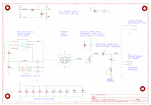
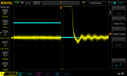
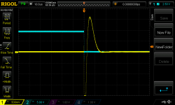
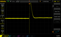
Using Quasimodo with just C3/Cs shorted was straightforward. I could trigger off a pin connected to the left side of C2 (see Quasimodo_V4_TH_sch.png attached here for ease of reference) in the usual fashion. Ringing from the transformer was most prevalent when the driving FET drain went low and so I focussed my optimisation efforts there. Attached are scope pics for Rs 345R, 165R and 154R, respectively. The latter value seemed a bit more optimal when viewed with much greater vertical resolution.
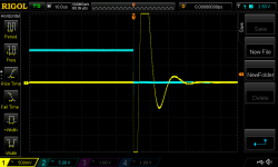
Shorting C2/Cx, however, was a little more problematic. I immediately lost my ability to trigger the scope as before and so had to trigger from Channel 1, the transformer secondary waveform. Attached are scope shots for 912R and 415R, respectively.
Clearly the dissipation of Rs for the latter scenario is considerably more than for the case Mark examined above and attempting to snub without Cs and Cx is likely inadvisable.
I recently purchased some PCB transformers from the Block range. Today I coupled up a PT series 7.5VA 2x15V transformer to my Quasimodo jig to look at snubber optimisation without the use of the series capacitor "Cs" and the parallel capacitor "Cx" as per the conversation above and also mentioned here.
Using Quasimodo with just C3/Cs shorted was straightforward. I could trigger off a pin connected to the left side of C2 (see Quasimodo_V4_TH_sch.png attached here for ease of reference) in the usual fashion. Ringing from the transformer was most prevalent when the driving FET drain went low and so I focussed my optimisation efforts there. Attached are scope pics for Rs 345R, 165R and 154R, respectively. The latter value seemed a bit more optimal when viewed with much greater vertical resolution.
Shorting C2/Cx, however, was a little more problematic. I immediately lost my ability to trigger the scope as before and so had to trigger from Channel 1, the transformer secondary waveform. Attached are scope shots for 912R and 415R, respectively.
Clearly the dissipation of Rs for the latter scenario is considerably more than for the case Mark examined above and attempting to snub without Cs and Cx is likely inadvisable.
Attachments

Last edited:
The Quasimodo design note pp.12-13 talks about how to use Quasimodo to optimize a 2 element snubber (Rs and Cs but no Cx). Allow me to suggest that you consider this approach ... using Cs=Infinity. An infinite capacitor is of course a short circuit. This little trick was also used in the Appendix of the Soft Recovery article in Linear Audio; it simplifies the analysis.
Following p.12-13 you can use Cx=(summation of terms) when dialling up the optimum R on a Quasimodo board. In fact, that's what I would do. That's what I have done, myself, more than once.
Following p.12-13 you can use Cx=(summation of terms) when dialling up the optimum R on a Quasimodo board. In fact, that's what I would do. That's what I have done, myself, more than once.
I'm not sure I see a compelling reason to discard the CRC snubber. The potential to drop two caps per secondary from my PCB was worth pursuing but dropping one per secondary gets close to being neither here nor there. (Incidentally, with this little transformer and Cs=150n and Cx=10n, Rs came out at 176R or so.)
If you decided to use this £0.19 capacitor you could lay out the entire RC snubber on your PCB using only two thru-holes (instead of four), spaced only 0.2mm apart. How do you think Japan Inc. built 9-Transistor radios with 4 IF transformers, on a 3" by 3" PCB, in 1963? If they can do it, you can do it.
If you decided to use this £0.19 capacitor you could lay out the entire RC snubber on your PCB using only two thru-holes (instead of four), spaced only 0.2mm apart. How do you think Japan Inc. built 9-Transistor radios with 4 IF transformers, on a 3" by 3" PCB, in 1963? If they can do it, you can do it.
0.2 cm? 0.2 millimeters is _really_ close together, dude.
0.2 cm? 0.2 millimeters is _really_ close together, dude.
Yes you're right. I've got my PCB CAD system set up in imperial units so when thinking about boards I use mils. In this case I was attempting to say that the two PCB thru-holes will be spaced 75 mils, center to center. When I tried to convert that to metric I bungled the decimal point. The correct spacing is 1.91 millimeters, which I suggest you round up to 2.0 mm. Sorry for the careless mistake.
I recently tested three new transformers, and here is a new version of my Excel table containing now snubber data for a total of some 13 transformers.
There is again good agreement between the Rs values obtained by means of the Quasimodo jig (the third column from the right) and those calculated on the basis of the natural (resonant) frequency (the last column). The latter is explained in post #593 on the link
http://www.diyaudio.com/forums/powe...rmer-snubber-using-quasimodo-test-jig-60.html
I would be happy to add the snubber data obtained by other Members to the table as they become available, and publish the updated table in the thread. However, since the table already has a certain functionality built-in, in that it not only lists the snubber data obtained by means of the jig, but also compares these with the theory of Hagerman, a candidate data set to be entered into the table should contain the following items:
- The essential transformer data (the first three columns)
- The secondary resistance (welcome, but not essential)
- Natural (resonant) frequency with Cx=10nF (essential)
- Damping factor and Nat. freq. with Rs=0 (not essential)
- Zeta,opt fow which Rs was determined with the jig (essential)
I can maintain the table in the Excel (Version 97-2003, 2010) and ODS formats.
My current table is enclosed in the above two spreadsheet formats and in PDF.
Regards,
Braca
Attachments
- Home
- Amplifiers
- Power Supplies
- Simple, no-math transformer snubber using Quasimodo test-jig