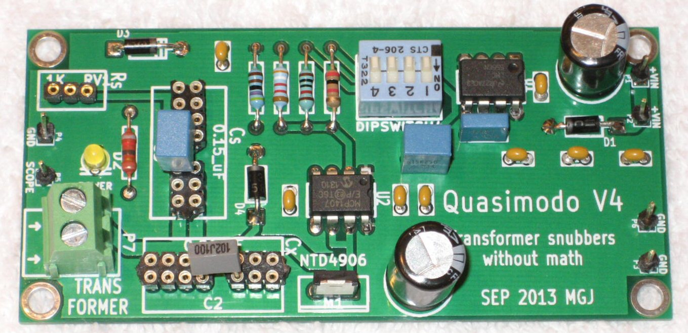
The sockets for C2 and C3 have many many pins, which allows you to plug in a huge variety of different capacitors, regardless of lead spacing. If your capacitor has very small lead spacing, plug it into the socket holes which are close together. If your capacitor's leads are spaced very far apart, plug it into the socket holes which are far apart. Here is a photo of a completed V4 Quasimodo with a very small capacitor C2 (gray box). It is plugged into the socket holes which are closest together. As you can see, the socket can accommodate a C2 with much longer body, if required.
To make this possible, all six socket pins for TERMINAL-1 are shorted together, as you observed. All eight socket pins for TERMINAL-2 are shorted together as well.
_
To make this possible, all six socket pins for TERMINAL-1 are shorted together, as you observed. All eight socket pins for TERMINAL-2 are shorted together as well.
_
Attachments
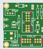
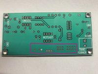
It's clean what you wrote. But the all pads of the selected area are shorted together through ground. I do understand that the error is at my side, and lots of successful implementations were done. But how can I explain it to the pcb supplier?The sockets for C2 and C3 have many many pins, which allows you to plug in a huge variety of different capacitors, regardless of lead spacing. If your capacitor has very small lead spacing, plug it into the socket holes which are close together. If your capacitor's leads are spaced very far apart, plug it into the socket holes which are far apart. Here is a photo of a completed V4 Quasimodo with a very small capacitor C2 (gray box). It is plugged into the socket holes which are closest together. As you can see, the socket can accommodate a C2 with much longer body, if required.
To make this possible, all six socket pins for TERMINAL-1 are shorted together, as you observed. All eight socket pins for TERMINAL-2 are shorted together as well.
Oops, I apologize to @dzoli , I misunderstood your message.
In my opinion, you probably did nothing wrong and the error was made by the PCB manufacturing house. As you mentioned, the Gerber files are known to be good and they have been successfully fabricated by hundreds of diyAudio members at PCB fabs around the world.
I have a few suggestions for things you can do.
1. Make sure you sent the file whose name is exactly qmodo_TH_Gerbers_for_seeed.zip to the PCB fab.
2. Check whether your PCB fab's website includes a "Gerber Viewer" page or tab or app. Use that to view the Gerber file which you sent them. Study the area of the bottom PCB layer where your error occurred, and check whether their software thinks those pins SHOULD be shorted. (the correct answer of course is "no they shouldn't"). If you see the pins NOT shorted, take a screen capture image of that area and complain to the fab that they built your boards with errors and you want an immediate refund.
3. Choose a different PCB fab and place a new order for boards there. Personally, I am fond of JLCPCB.com and I wrote this little tutorial about buying boards from them. Lots of diyAudio members around the world have used JLCPCB.com successfully. They are usually the lowest price supplier too.
4. Create a new thread in the swap meet forum of diyAudio saying: Wanted To Buy, 3 PCBoards of Quasimodo Thru-Hole V4 . Also post a message here on the Quasimodo thread saying the same thing.

Hello, I hope I can post this here. I bought a V4 quasiomodo PCB from ebay (28 USD with the shipping!!) and all parts from the BOM I found on this thread (thank you). That was another 50 USD. I was looking forward to building the quasimodo jig and using it to get the R value for a snubber in a phono amp power supply (the Pearl 3), BUT I got the instructions wrong and soldered the transformer in, thinking it had to be in the circuit before using the quasimodo and the scope to obtain the optimal R value. Sadly I ended up looking up the otpimal value for my transformer on a list. So now I have no use for it and I am wondering if anyone would like to buy the pcb and parts for about .... 65usd + shipping to wherever you are? If interested I will send you an accurate list of all the parts. To be clear, nothing was soldered, all parts and pcb are unused, unsoldered.
Heya Mark, Quasimodo V4 boards are a 2013 concoction. I was wondering if maybe we could do a V5 board for 2025?
Here's some ideas. V5 would be considerable smaller and simpler (and cheaper maybe). Ppl that still need V4 can still use V4.
1. New design to accomodate SMD driver and Power MOSFET package but keep the rest through thru-hole.
2. No 555 generator. Instead lets just assume everyone has a Waveform or Function Generator... BNC input straight to the MOSFET gate driver.
3. Assume people have Scopes... BNC output for direct attach to the scope.
4. 9V battery powered. You can always borrow the 9V Lithium from your nearest smoke detector for the very short periods of time you need to 'modo.
Very low Z source of current here.
5. Big Fat Traces to DUT connection... Euroblocks are fine still... Maybe another BNC assuming Banana Post ? Maybe option for both?
…perhaps Cheapomodo?
A high quality test-jig called Quasimodo has been described on diyAudio; it helps you find the optimum value of transformer snubber components without using mathematics.
As presented in that thread, Quasimodo is a no-compromise design using a state of the art vertical MOSFET with Rds(on) < 0.01 ohms, and an insanely powerful gate-driver IC with 6.0 ampere output current. It works best on a 2 layer PCB with a groundplane and careful layout.
But some people might want to slap together a snubber test-jig on their solderless breadboard ("proto board") and not worry about amps of...
- Mark Johnson
- Replies: 342
- Forum: Power Supplies
Hello @jrdmedford , please go right ahead with your redesign! Please accept my blessings and good wishes for complete success.
It may be helpful if I inform you that I've gotten LOTS of private messages over the past decade+, enthusiastically thanking/praising me for the fact that Quasimodo can run from a 9V battery with only an oscilloscope connected, and zero other pieces of external equipment. No DC power supply, no signal generator, no USB interface to a computer, nada. Just a battery and a scope -- which frequently is a handheld battery powered scope. In those cases, Quasimodo can accomplish its job on a kayak in the middle of the Columbia River, with no AC mains whatsoever.
I will not be participating, except of course to cheer for your victory. Good luck and God Speed.
Complete newb here. I’m calculating R for the AnTek AS-1218 and am confused on why the shape is different when the coils are in parallel vs. a single coil? The results from the parallel connection is a bit deformed compared to a single coil. The single coil is textbook.
Attachments
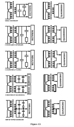
Please post two drawings, similar to Figure 13 of the Quasimodo Design Note, showing exactly what you mean by (a) "when the coils are in parallel"; and (b) "a single coil".
Be sure to copy the Fig 13 style; show how it will be connected in the final audio equipment on the left, and also show how it is connected during Quasimodo testing on the right. The thick black lines on the right hand side, are short-circuit connections that you make with alligator clips or wire nuts or blobs of solder, for Quasimodo testing.
_
Attachments
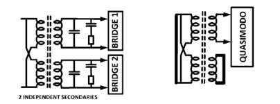
“Please post two drawings, similar to Figure 13 of the Quasimodo Design Note, showing exactly what you mean by (a) "when the coils are in parallel"; and (b) "a single coil".
Be sure to copy the Fig 13 style; show how it will be connected in the final audio equipment on the left, and also show how it is connected during Quasimodo testing on the right. The thick black lines on the right hand side, are short-circuit connections that you make with alligator clips or wire nuts or blobs of solder, for Quasimodo testing.”
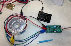
Thanks for replying. Pictured is the diagram I’ve referenced and a photo of my setup up in parallel.
Be sure to copy the Fig 13 style; show how it will be connected in the final audio equipment on the left, and also show how it is connected during Quasimodo testing on the right. The thick black lines on the right hand side, are short-circuit connections that you make with alligator clips or wire nuts or blobs of solder, for Quasimodo testing.”
Thanks for replying. Pictured is the diagram I’ve referenced and a photo of my setup up in parallel.
Attachments

Hey everyone, I would love to try the quasimodo jig for a phono build and curious if there is a way to borrow or rent one from someone?
Apologies if not appropriate to ask 🙂
Apologies if not appropriate to ask 🙂
Totally fine to ask. 🙂
I suspect the actual most straightforward and cheapest solution is finding a Cheapomodo board, it’s very inexpensive to build and works as well as normal Quasimodo.
Does anybody have a spare Cheapomodo board?
I suspect the actual most straightforward and cheapest solution is finding a Cheapomodo board, it’s very inexpensive to build and works as well as normal Quasimodo.
Does anybody have a spare Cheapomodo board?
@thebadsolder - If you cover postage, I'll happily loan you mine. I checked, and I thought I may have a spare SMD version, but it seems to have flown the coop.
However, an alternative is that someone may have already measured the transformer(s) you plan to use and/or may have both the transformer(s) along with a Quasimodo jig and could measure them and share the measurements if they're not already posted in the 'results thread'. I admit to having tested a few and neglected to post results. Have you posted the make / model of the transformers publicly?
However, an alternative is that someone may have already measured the transformer(s) you plan to use and/or may have both the transformer(s) along with a Quasimodo jig and could measure them and share the measurements if they're not already posted in the 'results thread'. I admit to having tested a few and neglected to post results. Have you posted the make / model of the transformers publicly?
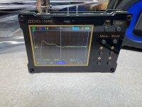
Finding Sadfaces posts have helped a bunch in trying to dampen my AS-1218 wired in parallel. Similar to Sadface, I ended up increasing Cx and Cs to 0.74uf and 0.045uf respectively. Rs is 14 ohms. I have some more capacitors of varying values showing up at the end of the week so I can try more combos.

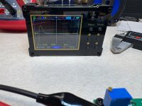
A photo of the result with Cx = 0.15uf and Cs = 0.01uf with Rs = 22 ohms for reference.

A photo of the result with Cx = 0.15uf and Cs = 0.01uf with Rs = 22 ohms for reference.
I have a bunch of Cheapomodo boards and the parts to populate. I shall send your way. @thebadsolder , please send me your address in a private message.Does anybody have a spare Cheapomodo board?
Oh I didn’t know about the results thread! That is great. I’ll take a look there tonight.@thebadsolder - If you cover postage, I'll happily loan you mine. I checked, and I thought I may have a spare SMD version, but it seems to have flown the coop.
However, an alternative is that someone may have already measured the transformer(s) you plan to use and/or may have both the transformer(s) along with a Quasimodo jig and could measure them and share the measurements if they're not already posted in the 'results thread'. I admit to having tested a few and neglected to post results. Have you posted the make / model of the transformers publicly?
I am running two AS-1215 - 100VA 15V into a PSU (wired in series to each provide 30 vac).
If I can find something on the results thread, I’d be happy to cover postage to you or @birdbox. Thank you both for the offer.
- Home
- Amplifiers
- Power Supplies
- Simple, no-math transformer snubber using Quasimodo test-jig