To select a frequency of 2500 Hz, for example, do you have just switch 3 on and all others set to off, or do you need to have switches 1, 2, and 3 all turned on?
Many thanks,
John
Many thanks,
John
Take a look at post # 1,466 of this thread. If you're using the default preference of 20 posts per "page" , post 1466 appears on page 74.
Thanks Mark. So the switches parallel the resistors per that chart and the resulting frequencies are displayed.
I assume there is a reason that you can vary the frequency; namely that the snubber resistance value will change. If that is correct how do you determine what frequency is optimal for determining the snubber resistance value for a particular transformer?
I'm a mere implementor, not an electrical engineer. But I'm interested in how these things work.
Thanks for creating Quasimodo,
John
Your variable frequency question is answered in Quasimodo posts #1,214 and #2,460 and post #14 of the Cheapomodo thread.
Look for a three letter acronym, and also look for the character string "... might want to monkey around with the DIPswitches ..."
Look for a three letter acronym, and also look for the character string "... might want to monkey around with the DIPswitches ..."
Wow Mark, you thought of everything! I'm using a new Hantek inexpensive digital scope so the frequency shouldn't be an issue. But some of the guys in audio do prefer the analog CRT based scopes, so putting in the frequency selector was a good call.
I know you must get tired answering the same questions over and over. I did try to do a search. I do apologize for the bother.
John
I know you must get tired answering the same questions over and over. I did try to do a search. I do apologize for the bother.
John
My first project e2e. Measured Rs for Hammond 1182M15 as 16.9Ohms in independent parallel mode.


NeoTheOne,
I am about to build the Quasimodo. In your bottom picture the transformer connects to P7. P4 is the scope ground and P5 is the scope signal. What is attached to P2 and P6 on the right-hand side of the pcb?
Many thanks,
John
I am about to build the Quasimodo. In your bottom picture the transformer connects to P7. P4 is the scope ground and P5 is the scope signal. What is attached to P2 and P6 on the right-hand side of the pcb?
Many thanks,
John
P2 and P6 connect to 9v power supply. The jig is drawing 20 mili amps of current.
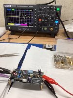
For reference I have a benchtop power supply (see the red and black banana plugs attached to it. they directly connect to the quasimodo board on the right hand side.)

For reference I have a benchtop power supply (see the red and black banana plugs attached to it. they directly connect to the quasimodo board on the right hand side.)
Last edited:
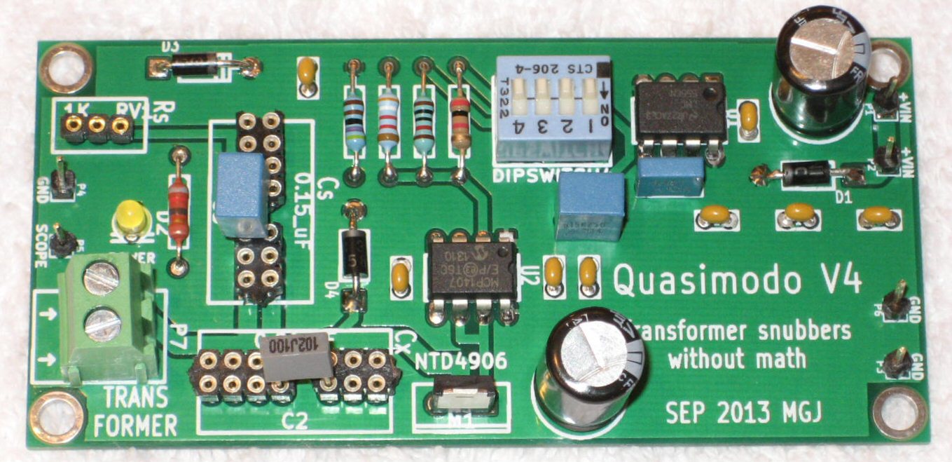
The PCB connection posts have labels on the top silkscreen layer, telling you what signal they carry. You can see the labels more clearly in this photo (which I've borrowed from post #54):
_
_
Thank you Neo and Mark. I have a Uni T bench power supply that I can use to power the board. I should get the components for the board which I ordered from Mouser on Wednesday.
John
John
Re-thinking powering the Quasimodo board. Mark's white paper says to power the board with a +15V. The Siglent supply in the picture above is using +/-9 V. Without seeing this I would have set it for +15V and used the red terminal and the green ground terminal on the power supply.
What is it that I don't understand about powering the Quasimodo?
Confused again....
What is it that I don't understand about powering the Quasimodo?
Confused again....
From @mvaldes to me
To operate the Quasimodo you need to:
1.- connect a power source to Vin e Gnd (2.6 to 18Vdc) (two Vdc connector are there just for redundancy)
2.- connect the secondary of transformer to P7
3.- connect the scope probe to p4 / P5
3.- short the primary of trasformer
4.- insert the Cx, Cs and Rs components in their respective socket (use the value suggested by Mark)
5.- turn on the Quasimodo power and look the result on the scope screen
6.- adjust the Rs trimmer until you get the correct dumped figure on the scope
7.- take out Rs trimmer form his socket and misure it with a multimeter. This will be the Rs value
at this point you have the correct Rs, Cx and Cs value to correctly dumping that specific transformer

That is correct, the P1 or p2 goes to positive of power supply and P6 or P5 goes to negative of power supply. You can apply 2.6-15 VDC as input to the board.Without seeing this I would have set it for +15V and used the red terminal and the green ground terminal on the power supply.
🤣 yes, your guess is definitely correct."damp" rather than "dump" I would hazard a guess
Ok guys, I followed Neo's script above except that I powered the Quasimodo board with +/-12 DC volts using my bench power supply. The first photo is the scope reading without the trimpot installed (infinite resistance) per Mark's suggestion. Then I installed the trimpot and adjusted it until the line was flat. Measuring the resistance necessary to accomplish this I get 13.3 ohms.
The transformer is a Toroidy 500 VA with dual 50 V secondaries.
Let me know is this looks reasonable. Also, what causes suck out in the middle of the trace in the second photo?
Many thanks for your help with this (especially Mark and Neo),
John
The transformer is a Toroidy 500 VA with dual 50 V secondaries.
Let me know is this looks reasonable. Also, what causes suck out in the middle of the trace in the second photo?
Many thanks for your help with this (especially Mark and Neo),
John
Attachments

Hi guys. It’s my first post on this forum.
I am always grateful for evey useful information.
English is not my tongue, please pardon me if there are strange words..
I built a tube guitar amp a while ago.
It had faint buzz on high frequency.
I couldn't figure out what was causing it, but I thought it was probably a transformer problem.
Today, I installed CRC snubber and..
surprisingly, the buzz is gone!
..However, I realized I had a mistake.
I installed it just like this;

I should installed them on each winding, not just like this.. right?
However there is no issue so far, fortunately. and It’s obviously effective and working well, since the buzz is gone.
The amp is functioning normally.
This is high voltage circuit(340v-0-340v), I have no spare HV capacitor right now. (I used 1KV MKPs)
I’ll order the components later and fix this..
If it is done this way, what potential problems can be expected?
EDIT : I’v read a thread after I posted this.
according to this, I’ll be fine.. I used SiC diodes, so the diode snubbing is not my concern.
Another question remains, rating of the snubber.
the snubber seeing pretty large voltage now : 680v~700v AC. the capacitors rated 1kV. I don’t know well about peak voltage(?) in snubbering, I wonder 1kV would be suffice.
I am always grateful for evey useful information.
English is not my tongue, please pardon me if there are strange words..
I built a tube guitar amp a while ago.
It had faint buzz on high frequency.
I couldn't figure out what was causing it, but I thought it was probably a transformer problem.
Today, I installed CRC snubber and..
surprisingly, the buzz is gone!
..However, I realized I had a mistake.
I installed it just like this;
I should installed them on each winding, not just like this.. right?
However there is no issue so far, fortunately. and It’s obviously effective and working well, since the buzz is gone.
The amp is functioning normally.
This is high voltage circuit(340v-0-340v), I have no spare HV capacitor right now. (I used 1KV MKPs)
I’ll order the components later and fix this..
If it is done this way, what potential problems can be expected?
EDIT : I’v read a thread after I posted this.
Hi guys,
what's the recommended method for adding a snubber across the secondary of a transformer if it's centre tapped and being used with a 2 diode full wave rectification?
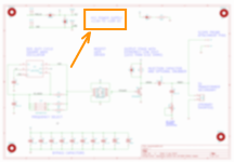
Do you only need a single snubber across the 2 outer wires, ignoring the centre tap or is it better to have 2 lots of snubbers going to the centre tap like this?

I did a bit of searching around but couldn't find a definitive answer.
thanks,
James
what's the recommended method for adding a snubber across the secondary of a transformer if it's centre tapped and being used with a 2 diode full wave rectification?
Do you only need a single snubber across the 2 outer wires, ignoring the centre tap or is it better to have 2 lots of snubbers going to the centre tap like this?
I did a bit of searching around but couldn't find a definitive answer.
thanks,
James
- dwjames
- Replies: 6
- Forum: Power Supplies
according to this, I’ll be fine.. I used SiC diodes, so the diode snubbing is not my concern.
Another question remains, rating of the snubber.
the snubber seeing pretty large voltage now : 680v~700v AC. the capacitors rated 1kV. I don’t know well about peak voltage(?) in snubbering, I wonder 1kV would be suffice.
Last edited:
- Home
- Amplifiers
- Power Supplies
- Simple, no-math transformer snubber using Quasimodo test-jig