Pretty much any of the pictures with Rs <= 19R look acceptable. HOWEVER, I recommend operating with Cs >= (15 * Cx) just so the damping resistor is effectively in series with (a short circuit) for every circumstance. The bigger the capacitance, the better the short circuit. Based on the 15X criterion, I would reject and eliminate from consideration any test performed with { Cs=1000nF and Cx>20nF }. I think the 15x concept is buried in the Quasimodo design note somewhere.
The picture that looks most beautiful to me is (Cx=10nF , Cs=1uF , Rsnub = 17.4R). Then just buy an 18 ohm, 0.6 watt, flameproof resistor and be happy. You're so much better than the first photo (R=infinity); it's not productive to haggle over the final 5 percent.
The picture that looks most beautiful to me is (Cx=10nF , Cs=1uF , Rsnub = 17.4R). Then just buy an 18 ohm, 0.6 watt, flameproof resistor and be happy. You're so much better than the first photo (R=infinity); it's not productive to haggle over the final 5 percent.
I would have thought 1000nF/68nF = 14.71 was close enough to 15.( I did the rough calculation in my head at the time and it felt about right).
However, I agree on not chasing the last 5%. Especially when I probably only understand a fraction of what is going on here.
10nF + 1uF + 18R frame proof it is.
Regarding capacitor selection. Is it a good idea to use class X2 caps here?
I am thinking that on the 230v secondary, this is effectively an across the mains line application. Thus requiring class X2.
Hey all,
So I have been building a parts list on digikey and I have a few questions. I went ahead and made the list public so others can see it. I know for sure its not right but I wanted to pass it by folks here for review and thoughts on what I selected and also more importantly on the things they are out of stock on.
First - the list. I also saved a version of the BOM to google which has a column for the digi part I chose in case anyone wanted to look at it that way.
My questions:
In case its not obvious to folks happening upon this post - don't order from that list 😉 I may adjust the tag once people have given feedback / verified but use the bom from the author 😉
So I have been building a parts list on digikey and I have a few questions. I went ahead and made the list public so others can see it. I know for sure its not right but I wanted to pass it by folks here for review and thoughts on what I selected and also more importantly on the things they are out of stock on.
First - the list. I also saved a version of the BOM to google which has a column for the digi part I chose in case anyone wanted to look at it that way.
My questions:
- C1 - I think I picked the right part but could someone else verify it? I was a little unsure on what is needed there
- RV1 - the trim pot, I think I selected the right one?
- C2 / RV1 - The parts in the bom are unavailable so I went hunting for something similar
In case its not obvious to folks happening upon this post - don't order from that list 😉 I may adjust the tag once people have given feedback / verified but use the bom from the author 😉

From your parts list, it seems you're building the SMD version. Is that what you wanted?
Moving on -
1 - C1 / C3-C13 look fine to me. One more confirmation than mine is always a good thing.
2 - Looks good to me. One more confirmation than mine is always a good thing.
3 - C2 - If I'm looking correctly, you've provided the part number for a 10pF ceramic cap, K100J15C0GF53L2. I use film caps with about 1,000 times more capacitance in that position. One example is, B32529C3103J. One more confirmation than mine is always a good thing.
The sockets are for installing / removing the Cs (C3), Cx (C2), and Rs (RV1). You can (if you choose) install Cs and Cx permanently on the board. As one example, I trust those values, and I don't see any use cases where I would change them. I use the same parts I use in-circuit for my PSU builds. That's not necessary, but it makes me feel warm and fuzzy. You'll likely be removing Rs and checking it for each measurement, so a socket is nice.
tl;dr - you can use pretty much any standard pitch socket there. I'm reasonably sure, I bought a bunch of the "breakaway" type sockets from Amazon.
Last edited:
Anyone have any spare V4 PCBs? If not, I'll order from JLCPCB and then I'll have some available.
I have 4 and will part with 2 for shipping costs. Still debugging the one board I built up. Message me.
I ordered 3 of the v4 surface mounts and only need 1. PM me if you want to buy one of the other 2. I'm just going to divide the order total by the number of boards - iirc total was like 17 for 3.Anyone have any spare V4 PCBs? If not, I'll order from JLCPCB and then I'll have some available.
I got word from oshpark they are being cut yesterday so I should have them in a few days maybe? Not sure what the shipping lead time is
Like others on this thread I don’t have an oscilloscope. I have been debating buying one for some time and now have a legitimate excuse. I have built both solid state and tube amps/preamps (one of which has a hum in one channel that I need the tools to diagnose) and plan on building more. Can I ask for a recommendation for one that will grow with me as I figure things out? Cost is always a consideration, but since this is a long term purchase functionality is more important. Thanks!
Hi Mark Johnson & all,
I recently ordered some through-hole Quasimodo PCBs from JLCPCB and now have built and tested a PCB. And I am indeed very satisfied with the result ... So much easier to adjust the response of the transformer interface and attenuate the oscillations that were otherwise there! So a big thanks to Mark Johnson for designing and making available this circuitry with PCBs 😉 😊
Also, should anyone here need a PCB I now have 3 spare ones (through-hole PCBs) that you can have for the cost of shipping (FYI I live in Denmark).
@TomR. : Hi Tom ... Just briefly as there are other threads on diyaudio discussing oscilloscope recommendations ... Considering a recommendation for an oscilloscope that will grow with you, I would suggest looking at Siglent's relatively new 12 bit oscilloscopes. Something like the SDS800X series where the basic model (70 MHz bandwidth, two channels, 12 bit resolution) - at least about a years ago - was available at appr. USD 299.
https://siglentna.com/digital-oscilloscopes/sds800x-hd-digital-storage-oscilloscope/
Cheers & thanks again, Mark!
Jesper
Last edited:
Reading this thread with interest, since I always bypassed the PSU diodes due to the "RF mixer diode" effect. In fact, this is amply used in the commercial equipment like old CRT TV's to avoid RF mixing in the PSU diodes and suchlike effects (this maybe can produces some patterns in the image of old analog TV's, according with the offending signals). So, even for '60's TV's we found these caps in parallel with the diodes. Normally being from 1 to 5nF.
I also think about the reduction of the reverse recovery loop of the diodes, and this implies the cap needing to be connected directly to the diode terminals. No cap implies that the reverse recovery current needs to travel across all the PSU elements.
Too many posts to remember, but someone here mentioned about RF being irradiated and detected by a AM radio. Well, the ringing are in these range sometimes, but perhaps the recovery currents and mixer effects are more seen at VHF range (ns of recovery)?
I perhaps can be missing something or overrating some other things, but, even with several years into this hobby, I'm learning new things sometimes 🙂
All of this neglects the trafo ringing, and I'm convinced about it's importance. Since, after all, the common PSU are a hard rectfiying the incoming voltage, and this makes a large room for great ringing when diodes are all reverse biased (for example).
But I'm interested in mixing the methods: using relatively low value caps for the "recovery" current of the diodes, not messing so much with the fixed Cx. I can also use a somewhat higher value for that. I can imagine perhaps 1nF for the diode caps, 15-22nF for the Cx cap and 150-330nF for the cap in series with the damping R. Perhaps the 1nF for the diode not upset too much a 22nF Cx cap.
For my next PSU I can test it.
I'm thinking to use a square wave oscillator that I have, buffer it's outputs and use some low rds MOSFET that I have, for making the tests. Mixing some laziness ;-) with using parts at hand for cheap and fast option, at least for now.
I already built SMPS in the past, and determined empirically the snubbers. Worked well. But with already fast waveforms of the SMPS world, is directly applicable the measurements. The Quasimodo boards are excellent for making this in the mains frequency based PSU (kudos for this great idea!).

Thank you Mark.
Would it possible to explain to me what should I be looking for when adjusting the resistance? It's not very clear to me why anywhere between 0:18 and 0:22 is perfection.
Am I trying to get the red arrow as flat as possible or the green one? In either case, why anything after the 22 sec is not good?
I've read many posts on this thread as well as the .pdf but it's still a bit unclear to me...
Attachments
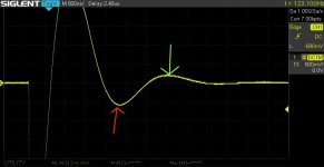
Thank you. The truth is that I have read all these posts together with many more. In a number of posts you recommend to stop as soon as the trough gets flat.
I must be stupid but I fail to see how 18-22sec is the correct resistor value. To me it looks that the trough (2nd lumpity/bumpity?) starts to get flat on the 25sec or thereabouts...
I must be stupid but I fail to see how 18-22sec is the correct resistor value. To me it looks that the trough (2nd lumpity/bumpity?) starts to get flat on the 25sec or thereabouts...
I have memory of using my test-jig before without problems. I am not sure what I am doing wrong this time.
Powered by +15V I get the clean triggering signal from CH1 and the same appears to CH2 (no transformer connected yet) as log as RV1 is out of the circuit. If RV1 is in place (no matter the value), CH2 drops into milli-volts amplitude and difficult to see on the scope.
If I connect the transformer secondary, I can see the ringing, but too noisy to do anything with it. Did I break my Quasimodo, or did I just fail my homework? 😳
People who weren't in the room with you when those tests were run, have no idea where "CH1" and "CH2" were connected. We don't understand your post.
I recommend
Test 1: remove RV1 from its socket, disconnect and remove everything from the transformer secondary Euroblox connector. Probe the signal network named OSC, adjust the horizontal sweep rate so there are two or three complete waveform periods, and take a photograph of the oscilloscope trace (single channel, single trace). Probe the signal network named FETGATE and take another photograph (single channel, single trace). Probe the signal network named DRAIN and take a third photograph (single channel, single trace).
Test 2: remove RV1 from its socket, connect an inductor whose inductance is known (printed on the inductor body) to the transformer secondary Euroblox connector. Probe the signal network named DRAIN and take a photograph of the oscilloscope trace. Probe the signal network named TRAFO and take another photograph.
Test 3: leave the known inductor connected to the transformer secondary Euroblox connector. Plug the variable resistor RV1 into its socket. Take three photographs of the oscilloscope trace, when (i) the trimmer knob is rotated 100% clockwise; (ii) the trimmer knob is rotated 100% anti-clockwise; (iii) the trimmer knob is at the halfway point.
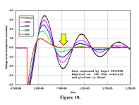
Test 4: with the known inductor and RV1 installed, slowly dial the trimmer knob until the oscillatory ringing matches the red trace in Figure 10 of the Quasimodo Design Note (.pdf attached to post #1 of this thread). Probe the signal network named TRAFO and take a photograph of the oscilloscope trace (single channel, single trace).
If you perform all four tests, and if Test 4 is a complete success -- you are able to make your Quasimodo board and your known inductor give an output which matches the red trace in Figure 10 -- then your Quasimodo board is working correctly. Any problems you may experience with other loads, are not problems with your Quasimodo board.
_
I recommend
Test 1: remove RV1 from its socket, disconnect and remove everything from the transformer secondary Euroblox connector. Probe the signal network named OSC, adjust the horizontal sweep rate so there are two or three complete waveform periods, and take a photograph of the oscilloscope trace (single channel, single trace). Probe the signal network named FETGATE and take another photograph (single channel, single trace). Probe the signal network named DRAIN and take a third photograph (single channel, single trace).
Test 2: remove RV1 from its socket, connect an inductor whose inductance is known (printed on the inductor body) to the transformer secondary Euroblox connector. Probe the signal network named DRAIN and take a photograph of the oscilloscope trace. Probe the signal network named TRAFO and take another photograph.
Test 3: leave the known inductor connected to the transformer secondary Euroblox connector. Plug the variable resistor RV1 into its socket. Take three photographs of the oscilloscope trace, when (i) the trimmer knob is rotated 100% clockwise; (ii) the trimmer knob is rotated 100% anti-clockwise; (iii) the trimmer knob is at the halfway point.
Test 4: with the known inductor and RV1 installed, slowly dial the trimmer knob until the oscillatory ringing matches the red trace in Figure 10 of the Quasimodo Design Note (.pdf attached to post #1 of this thread). Probe the signal network named TRAFO and take a photograph of the oscilloscope trace (single channel, single trace).
If you perform all four tests, and if Test 4 is a complete success -- you are able to make your Quasimodo board and your known inductor give an output which matches the red trace in Figure 10 -- then your Quasimodo board is working correctly. Any problems you may experience with other loads, are not problems with your Quasimodo board.
_
Attachments
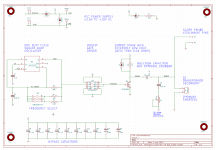
OSCTest 1: remove RV1 from its socket, disconnect and remove everything from the transformer secondary Euroblox connector. Probe the signal network named OSC, adjust the horizontal sweep rate so there are two or three complete waveform periods, and take a photograph of the oscilloscope trace (single channel, single trace). Probe the signal network named FETGATE and take another photograph (single channel, single trace). Probe the signal network named DRAIN and take a third photograph (single channel, single trace).
FETGATE
DRAIN
Test 2: remove RV1 from its socket, connect an inductor whose inductance is known (printed on the inductor body) to the transformer secondary Euroblox connector. Probe the signal network named DRAIN and take a photograph of the oscilloscope trace. Probe the signal network named TRAFO and take another photograph.
DRAIN
TRAFO with 0.4 mH inductor
TRAFO with 0.1 mH inductor
TRAFO with transformer secondary - Same test I was describing in my previous post, this time without RV1.
Is Test 2 considered a success?
Yes, if you display signal network TRAFO and trigger the scope on its falling edge, then speed up the horizontal sweep rate to 20 microseconds per division: I think you'll see a pretty good copy of the black trace in post #2,598 (which is Figure 10 of the Quasimodo Design Note, attached to post #1 of this thread).
If you do get a pretty good copy of the black trace, I'd say that equals success on this test.
If you do get a pretty good copy of the black trace, I'd say that equals success on this test.
- Home
- Amplifiers
- Power Supplies
- Simple, no-math transformer snubber using Quasimodo test-jig