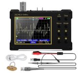
... ZEEWEII-154Pro (emphasis on Pro), for about USD 40 on eBay . . . . Claimed bandwidth is 18 MHz and . . . . .
I have been notified that some eBay sellers offer the ONE Megahertz version of this scope, while others sell the EIGHTEEN Megahertz version. Read the listings carefully!! Double check the exact model number!! Double check the specs in the listing itself.
What a rotten thing to do to unsuspecting buyers. Caveat emptor!

That seems to be a bolted on bargain. The 18MHz one is UKP24.90. According to the seller it has an ARM processor, an FPGA and an unspecified ADC.
It is very small and pretty low resolution (320 x 240). But is is colour display. It comes with a probe (unspecified as x1 or x10) a BNC to croc clips, a USB charging cable, and what looks like a belt clip.
What it does not seem to do is be able to dump the data to a PC.
Running on a battery, it is of course able to take floating measurements, which is nice.
Mine came with those same two probes. (A) standard "P6100" high-hat probe, switchable between 1X and 10X, alligator clip ground lead, 1Megohms; (B) straight-thru 1X pair of alligator clips, zero ohms. The unit also includes a "signal generator" that can produce sine, square, triangle wave outputs up to 0.5 MHz.
Both Amazon and Temu sell a probe they call "P6100" which they claim is good up to 100 MHz. But is it really? And is it the same exact probe which ZEEWEII ships with this scope? Hard to be sure.
_
Both Amazon and Temu sell a probe they call "P6100" which they claim is good up to 100 MHz. But is it really? And is it the same exact probe which ZEEWEII ships with this scope? Hard to be sure.
_
Attachments
Last edited:
Your opinion is correct. Increased capacitance in the diode results in worse turn-off. A bigger diode means bigger charge storage. The leakage L is the other important parameter, and it is a function of transformer design, specifically the construction. Split bobbin designs are worse for ringing than toroids due to the difference in leakage inductance. It isn't the self-resonant frequency of just the transformer. The series combination of the diodes, the filter cap, and the leakage inductance combine to make a resonant circuit.Using multiple series ss diodes, in lieu of just a single ss diode, also has the effect of slowing the transition from on to off, as the voltage change from on to off is twice, and as such reduces the abruptness of the current change.
It's also why, imho, it is better to use a lower current rated ss diode that is still applicable (ie. if the supply is ok with a 1N4007 then there may be a noise disadvantage in using say a 1N4508, and similarly for UF styles, and certainly for bridges like choosing a 35A bridge in the hope that its robustness is the key benefit).
Here are some examples based on the circuit simulator schematic I posted before:
Triad Class 3 control former, FS48-750 C2, split bobbin, Z limited design had 19mH for leakage when in circuit with a GBL06 bridge. Blue is the transformer's secondary voltage, and yellow is the secondary current. Conditions are 120V in about 33V out at 130mA. The spike is shown in the first oscillograph below. There is little reverse recovery (Ch1, yellow), yet the spike is 150V.
Next is a Hammond 185D24. It has a 2.9mH leakage and is still a split bobbin but is not a Z-limited design. The in-circuit resonant frequency with a 1N4006 is 108kHz, then with a GBL06, it is 101kHz; with a KBL08, 95kHz, and with a large bridge, the MB256, it is 77kHz. The result is shown in the second image below. Conditions are 120V in about 33V out at 370mA. Yellow, Ch1, is the secondary current; Blue, Ch2, is the transformer's secondary voltage; magenta, Ch3, is the DC output voltage; and green, Ch4, is the input voltage. Note how the secondary voltage is "clipped," but the input voltage is still a sine wave. Spike is about 25V.
Finally, a toroid, the Avel D4002. With 1N4006, the frequency was 680kHz, significantly higher than the split bobbin designs. Even with the MB256, the spike was of a lesser magnitude than with the split bobbin designs. See the third oscillograph below. It clearly shows reverse recovery in Ch1. Spike is about 6V.
Testing with 1N5822 Schottky diodes resulted in zero spikes and no reverse recovery. See the fourth oscillograph below. However, looking a little further in time, in oscillograph 5, we see that there is an oscillation of about 500kHz, albeit of a very low magnitude.
This testing suggests that divided bobbins should be avoided, or perhaps it is better to say that good coupling between primary and secondary should be a design goal to reduce leakage L.
Bottom line: Reverse recovery is a minor contributor to the spikes; the leakage L (transformer design) is more critical, e.g., use toroids.
Using the Quasimodo is worthwhile to see if the magnitude of the resonance is a possible issue.
Attachments
-
 104Vin 33.0V at 0.5A no reverse recovery 1N5822 discontinious ring at 500kHz.png36 KB · Views: 121
 -
 104Vin 33.0V at 0.5A no reverse recovery 1N5822.png38.1 KB · Views: 115
 -
 120Vin 33.8V at 0.5A reverse recovery with spike magnitude and ring freq on MB256 bridge.png29.8 KB · Views: 121
 -
 Primary Input and Secondary output sine wave 0.37A load max 47VA 8.5us first ring.png44.2 KB · Views: 129
 -
 Start up showing spike in magnification 0.13A FS48 750 C2 expnad 1 3rd ring 8.4us.png41.7 KB · Views: 128
Might anyone have a spare SMD PCB they would share/sell? I thought I'd ask before placing an order 🙂
Hello all.
I built a Quasimodo V4 TH jig and bought myself a 'scope, and I have attempted to perform the test. I think I've done it successfully, however I'm very new to oscilloscopes so I basically twiddled knobs until the scale looked right and things stuck in the middle. Would someone mind terribly checking my work here?
Here's the Amgis L01-6365 under test, with the primaries in series as per 230VAC operation, then shorted:

Here is the ringing with the trimpot removed:

Here's what I dialed in:

Note that the result was no different to my eye with the primaries shorted all together as per 115VAC:

For the record, I got the same result as is recorded in the results-only thread (63ohms). Or, at least, that's what the results looks like with 63 ohms. Higher was a bit lumpier (just a rougher slope, no swings back into the negative), and any lower resistance started to compress everything vertically without really changing the shape of the slope. If that makes sense.
Does this look correct to you? Apologies for the Ch2 trace - I couldn't figure out how to hide it without turning it off and loosing the trigger reference.
(for those wondering, my jig is bolted to a spare PCB with some nylon spacers and some screw on rubber feet - works well to keep it stable)
I built a Quasimodo V4 TH jig and bought myself a 'scope, and I have attempted to perform the test. I think I've done it successfully, however I'm very new to oscilloscopes so I basically twiddled knobs until the scale looked right and things stuck in the middle. Would someone mind terribly checking my work here?
Here's the Amgis L01-6365 under test, with the primaries in series as per 230VAC operation, then shorted:
Here is the ringing with the trimpot removed:
Here's what I dialed in:
Note that the result was no different to my eye with the primaries shorted all together as per 115VAC:
For the record, I got the same result as is recorded in the results-only thread (63ohms). Or, at least, that's what the results looks like with 63 ohms. Higher was a bit lumpier (just a rougher slope, no swings back into the negative), and any lower resistance started to compress everything vertically without really changing the shape of the slope. If that makes sense.
Does this look correct to you? Apologies for the Ch2 trace - I couldn't figure out how to hide it without turning it off and loosing the trigger reference.
(for those wondering, my jig is bolted to a spare PCB with some nylon spacers and some screw on rubber feet - works well to keep it stable)
The long story made short is yes, that looks great!
🙂
You can see the ringing with the resistor removed, the scope is triggering at the right place to see the pulse and wave, and the differences with the primaries shorted and open is usually quite small.
Nicely done!
P.S., turning the various channels off is usually done with the numbered buttons corresponding to the probe - it may take an extra press or two cycle it through "off". Press "2" a couple of times and see if the trace disappears .
The long story made short is yes, that looks great!
🙂
You can see the ringing with the resistor removed, the scope is triggering at the right place to see the pulse and wave, and the differences with the primaries shorted and open is usually quite small.
Nicely done!
P.S., turning the various channels off is usually done with the numbered buttons corresponding to the probe - it may take an extra press or two cycle it through "off". Press "2" a couple of times and see if the trace disappears .
Thanks for that!
It's kinda funny that I could've just trusted to the results thread and left it at that, but this way at least I'm learning new things (and accruing new toys). On that, I'll definitely have to have a poke around in the 'scope settings and get to know the thing.
You are not the first to buy a scope so you can use Quasimodo... and you won't be the last.
The oscilloscope is an amazing tool, in no time at all you'll wonder how you lived without one.
😎
The oscilloscope is an amazing tool, in no time at all you'll wonder how you lived without one.
😎
The resistor value is a little too low // you cranked the knob a little too much.
Pay attention to BUMP-2 and ignore everything else. Dial the knob for best damping; it occurs when BUMP-2 rises up to just barely flatline. Not above flatline. Don't look at bump-1 or any other bump. Just raise BUMP-2 to flatline and declare victory.
_
Pay attention to BUMP-2 and ignore everything else. Dial the knob for best damping; it occurs when BUMP-2 rises up to just barely flatline. Not above flatline. Don't look at bump-1 or any other bump. Just raise BUMP-2 to flatline and declare victory.
_
Attachments

The resistor value is a little too low // you cranked the knob a little too much.
Pay attention to BUMP-2 and ignore everything else. Dial the knob for best damping; it occurs when BUMP-2 rises up to just barely flatline. Not above flatline. Don't look at bump-1 or any other bump. Just raise BUMP-2 to flatline and declare victory.
Ah. Understood. Thank you.
I've since soldered the transformer and resistor in place, so that's a bummer. Desoldering is my least favourite kind of soldering. Gotta be done though. I'll report back once I've tackled that and measured it correctly.
Don’t sweat it.
As we’ve found with many transformers and PSU, having it close is many, many times better than having no snubber.
As we’ve found with many transformers and PSU, having it close is many, many times better than having no snubber.
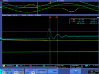
Figure 10 of the Quasimodo design note .pdf, attached to post #1 of this thread, shows a scope trace (the red line) with best damping. The yellow arrow points to the place where BUMP-2 rises up to just barely flatline.
Figure 10 of the Quasimodo design note .pdf, attached to post #1 of this thread, shows a scope trace (the red line) with best damping. The yellow arrow points to the place where BUMP-2 rises up to just barely flatline.
To be honest, I had some trouble getting my trace to behave in the neat and orderly fashion depicted, but that's likely down to my inexperience. I'll dust off the desoldering gun, extract the transformer, and have another crack.
Don’t sweat it.
As we’ve found with many transformers and PSU, having it close is many, many times better than having no snubber.
I hear you, but, I started on this whole thing to build the best ACP+ I could manage - I'm not quite ready to say 'good enough' just yet. 😂
Okay, so, I still hate desoldering, but it's done. Back to the drawing/bread board.
Here's the setup:

Here's the ringing with the trimpot removed:

Here's the ringing with the trimpot at 1k:

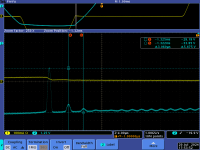
Here's the trace at 305 ohms:

Here it is at 183 ohms:

At 165 ohms:

And at 117 ohms:

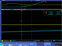
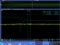
As you can see, it really doesn't want to flatten neatly. Here's the first two again at 10mV per division for further scrutiny.
305 ohms:

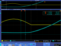
And 183 ohms:

You can see that with 305 ohms BUMP 2 is about 3mV above the flat line, but it's not flat, and takes a while to calm down.
183 ohms seems flatter, but it's actually lifted 35mV or so.
Not sure what to do here.
Thoughts? Suggestions?
Here's the setup:
Here's the ringing with the trimpot removed:
Here's the ringing with the trimpot at 1k:
Here's the trace at 305 ohms:
Here it is at 183 ohms:
At 165 ohms:
And at 117 ohms:
As you can see, it really doesn't want to flatten neatly. Here's the first two again at 10mV per division for further scrutiny.
305 ohms:
And 183 ohms:
You can see that with 305 ohms BUMP 2 is about 3mV above the flat line, but it's not flat, and takes a while to calm down.
183 ohms seems flatter, but it's actually lifted 35mV or so.
Not sure what to do here.
Thoughts? Suggestions?
The Quasimodo PCBoard uses a (ahem) highly engineered, spectacularly strong hammer blow, to ring the bell and ring it HARD. If you can damp out this ultra worst case ringing ON THE TEST FIXTURE beautifully and completely, then you can feel confident that it is damped even better and more thoroughly in the final audio equipment. And if you are only able to damp it out somewhat ON THE TEST FIXTURE, due to crappy probe calibration, crappy grounding, not being a seasoned oscilloscope wizard, or needlessly long test wires . . . . . it will still be damped better and more thoroughly in the final audio equipment.
Having said that, I think photo number 5 of 9, represents an acceptable stopping point. Not knowing whether the captions match the photos above, or below, the written text - - - - - I'll merely copy that picture. And as member @6L6 stated in post #2,552 : a well-meant, not very optimum, half decent snubber is fifty times better than no snubber at all. So don't get your knickers in a knot over the last 20% or so. Do your best, accept that experts might have minor quibbles, and realize this is plenty good and a fark tonne better than nothing.
_
Attachments
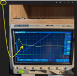
It's a way that I've seen suggested in this thread to trigger the scope with less hassle - it's on the other side of the cap from probe #1. The trace itself isn't otherwise relevant, from my understanding.What's the other probe doing?
Ha. That's fair. I had a feeling the leads weren't helping matters. The PCB pins on the transformer presented wiring issues I couldn't solve any other way with what came to hand, but I hear what you're saying. I tried to socket it to the breadboard, but the pins are offset just enough for that to be potentially damaging to the transformer, breadboard, or both. Next time around I'll look for a better solution.needlessly long test wires
Having said that, I think photo number 5 of 9, represents an acceptable stopping point. Not knowing whether the captions match the photos above, or below, the written text - - - - - I'll merely copy that picture. And as member @6L6 stated in post #2,552 : a well-meant, not very optimum, half decent snubber is fifty times better than no snubber at all. So don't get your knickers in a knot over the last 20% or so. Do your best, accept that experts might have minor quibbles, and realize this is plenty good and a fark tonne better than nothing.
Thank you for that. That photo is of the 183 ohm resistor trace (incidentally the same as in the final photo but 100mV per division rather than 10mV). I'll find what I have on hand around that value and call it done.
Thank you all for your advice. 🙂
- Home
- Amplifiers
- Power Supplies
- Simple, no-math transformer snubber using Quasimodo test-jig