Mark, I tried it but it just leads me back to https://linearaudio.net/
I will run some experiments and post afterward. Any comments on the type of transformer?
Any possibility of a synopsis of the results from the article from Linear Audio?
I will run some experiments and post afterward. Any comments on the type of transformer?
Any possibility of a synopsis of the results from the article from Linear Audio?
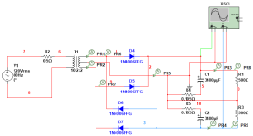
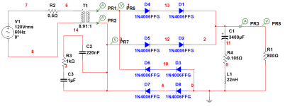
I decided to start with a couple of simulations. The first is a center-tapped full bridge with 1N4006 diodes using a spice model from ON Semi. The second uses 100V Schottky diodes in place of the 1N4006. The load is symmetrical (R1 and R3 have the same value), so no DC flows in the transformer. This is not a real-life application for audio, as the load will never be symmetrical.
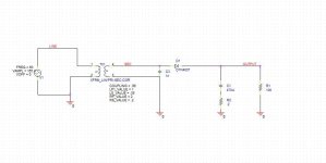
The transformer is a mythical unit based on a Multicomp pro torroid. It has a primary leakage L of 1mH and a leakage of 100uH for each secondary. DCR is 3 ohms primary and 0.14 ohms for each secondary. The turns ratio is shown on the schematics as 10 to 2, giving us an output voltage of about 30VDC with 120VAC input. The simulation is set to have a "perfect core," so no core losses are assumed.
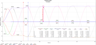
In the 1N4006 Big Pic, we see the start from zero volts on the input. The respective probe points are listed at the bottom. Note that the diode reverse recovery happens at zero current crossings and that this "abrupt" turn off "rings the bell."
In the next attachment, one can see the ringing enlarged and the data points that the simulator uses to calculate the various parameters.
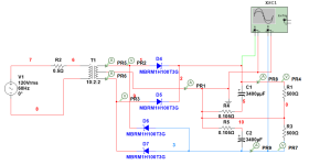
Tomorrow, I will post the results of the Shottky simulation.
Then, I will post comparative results a day after that.
I will also build the circuit and measure the actuals to compare to the simulation.
With no reverse recovery, I would like to see if the Schottky is better than the conventional diode.
Throwing darts at this is encouraged...
Ron
The transformer is a mythical unit based on a Multicomp pro torroid. It has a primary leakage L of 1mH and a leakage of 100uH for each secondary. DCR is 3 ohms primary and 0.14 ohms for each secondary. The turns ratio is shown on the schematics as 10 to 2, giving us an output voltage of about 30VDC with 120VAC input. The simulation is set to have a "perfect core," so no core losses are assumed.
In the 1N4006 Big Pic, we see the start from zero volts on the input. The respective probe points are listed at the bottom. Note that the diode reverse recovery happens at zero current crossings and that this "abrupt" turn off "rings the bell."
In the next attachment, one can see the ringing enlarged and the data points that the simulator uses to calculate the various parameters.
Tomorrow, I will post the results of the Shottky simulation.
Then, I will post comparative results a day after that.
I will also build the circuit and measure the actuals to compare to the simulation.
With no reverse recovery, I would like to see if the Schottky is better than the conventional diode.
Throwing darts at this is encouraged...
Ron
Attachments

If your interest is in the diode recovery operation/comparison, then perhaps some other sim circuit additions may be reasonable like a mains input impedance; secondary half-winding shunt capacitance; and loop inductance related to each first filter capacitance.
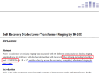
The Linear Audio website's page for the Soft Recovery paper (link) includes a little thumbnail at bottom left, labeled PDF Preview. When I right-click on that thumbnail (Firefox browser, Windows 11), I get a menu that includes "Open Image in New Tab". When I select Open Image in New Tab, I get a full size and easily readable image of page 1 of the Soft Recovery article, as published in the magazine. I've screen-captured that image straight off my browser+monitor; the top portion appears as attachment 1 below. Take careful notice of the red passage and also of the blue passage. The Abstract of the article includes the main conclusions . . . . . and boom-shakka-lakka-lakka-boom, there they are. Including your favorite word "Schottky".
There are several ways to legally obtain this article and support the wonderful efforts of Linear Audio (Jan Didden a/k/a @jan.didden ). One is to purchase the complete Linear Audio Library from the diyAudio Store (link 2). Another is to purchase a hardcopy of Linear Audio Volume 10, from Amazon (link 3). A third way to obtain this article is to send USD 2.90 by PayPal to the publisher, as mentioned right on the home page of Linear audio. I've copied it as attachment 2 below.
_
Attachments

The resistor, R2, represents the mains Z. I should have mentioned that. Thanks for pointing it out. As for the L of C1 and C2, it would be in the region of 22nH from 2MHz to 10MHz. This is a measured result of the electrolytic I'm using in the build (If there is interest, I can post the data). It did make quite a difference! In the first sim with 1N4006 the delta V of the ring was 403mV at 2.8MHz. With the addition of the parasitic L in the electrolytics the ring was almost double at 934mV at a frequency of 3.47MHz.If your interest is in the diode recovery operation/comparison, then perhaps some other sim circuit additions may be reasonable like a mains input impedance; secondary half-winding shunt capacitance; and loop inductance related to each first filter capacitance.
Very good input.
I ordered the USB stick.. thanks.The Linear Audio website's page for the Soft Recovery paper (link) includes a little thumbnail at bottom left, labeled PDF Preview. When I right-click on that thumbnail (Firefox browser, Windows 11), I get a menu that includes "Open Image in New Tab". When I select Open Image in New Tab, I get a full size and easily readable image of page 1 of the Soft Recovery article, as published in the magazine. I've screen-captured that image straight off my browser+monitor; the top portion appears as attachment 1 below. Take careful notice of the red passage and also of the blue passage. The Abstract of the article includes the main conclusions . . . . . and boom-shakka-lakka-lakka-boom, there they are. Including your favorite word "Schottky".
There are several ways to legally obtain this article and support the wonderful efforts of Linear Audio (Jan Didden a/k/a @jan.didden ). One is to purchase the complete Linear Audio Library from the diyAudio Store (link 2). Another is to purchase a hardcopy of Linear Audio Volume 10, from Amazon (link 3). A third way to obtain this article is to send USD 2.90 by PayPal to the publisher, as mentioned right on the home page of Linear audio. I've copied it as attachment 2 below.
_
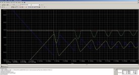
Now for the Schottky. It is worse in ring magnitude than the 1N4006. The value of the parasitic L in the electrolytics does not change the results significantly over the range of 10nH to 220nH.
| 1N4006 (conventional Diode) No snubber | Ring Magnitude 0.934V | Ring Freq 3.47MHz |
| MBRM1H100T3G (Schottky diode) No snubber | Ring Magnitude 1.52V | Ring Freq 1.0MHz |
Attachments
I'm afraid you aren't simulating the important aspects of diode induced ringing in a linear power supply with mains transformer, diodes, and filter capacitors. As member @trobbins tried to caution you in post #2,523.
Do another read-through of the Quasimodo design note (.pdf file) attached to post #1 of this thread, and carefully consider its very title: ... words ... words ... transformer snubber ... words ... words ... The problem is the transformer. The solution is to snub the transformer. That's what Quasimodo helps you do: figure out how to snub the transformer, without doing any math.
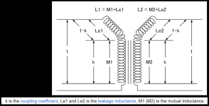
---> The problem is the transformer <--- and the easiest way to make the problem appear in circuit simulation, is to include the "leakage inductances" in the transformer model. These are inductances in the primary circuit and inductances in the secondary circuit, which are not flux-linked.
The easiest way to include leakage inductances is to tell the simulator that the transformer is non-ideal; its coefficient of magnetic coupling "K" between primary and secondary is non-ideal; its "K" is below 1.00. Yes indeed, real-world and real-life transformers are non-ideal and their winding-to-winding coupling is less than 1.00 .
After reducing K, simply include a little self-capacitance, say 200 picofarads across each secondary, and 100 picofarads across each primary*. That's all you need to do to start seeing oscillatory ringing in simulation.
Even using plain, ordinary, as-shipped-with-the-simulator, silicon diode models, Schottky diode models, and Silicon carbide diode models, you'll see plenty of oscillatory ringing. In fact it will ring in simulation, with ideal perfect filter capacitors (ESR=0 ; ESL=0). Because it's not the capacitors that are ringing. It's the transformer that is ringing. Its leakage inductance and self capacitance form a resonant circuit which rings like the dickens. The transformer is what rings. The transformer resonant circuit is the bell which rings. The diodes are merely the stimulus, the whack with a hammer, that induces the bell to ring.
Way back in the early 1970s, the great-grandfather of all simulators, Berkeley SPICE 2G6, let users create mutually coupled inductors (such as transformers) using the coupling coefficient K. See attachments 1, 2, 3 below. LTSPICE uses this same approach with the same syntax. I am not familiar with your simulator or its schematic notation in post #2,527 but I don't think I see "K=1" anywhere. Maybe it's a default? In any case, figure out how to have your simulator create partly-but-not-completely flux linked mutual inductors having K<1.
*see Appendix C and Figure 17 of the Quasimodo Design Note if you view these round numbers with suspicion.
_
Do another read-through of the Quasimodo design note (.pdf file) attached to post #1 of this thread, and carefully consider its very title: ... words ... words ... transformer snubber ... words ... words ... The problem is the transformer. The solution is to snub the transformer. That's what Quasimodo helps you do: figure out how to snub the transformer, without doing any math.
---> The problem is the transformer <--- and the easiest way to make the problem appear in circuit simulation, is to include the "leakage inductances" in the transformer model. These are inductances in the primary circuit and inductances in the secondary circuit, which are not flux-linked.
The easiest way to include leakage inductances is to tell the simulator that the transformer is non-ideal; its coefficient of magnetic coupling "K" between primary and secondary is non-ideal; its "K" is below 1.00. Yes indeed, real-world and real-life transformers are non-ideal and their winding-to-winding coupling is less than 1.00 .
After reducing K, simply include a little self-capacitance, say 200 picofarads across each secondary, and 100 picofarads across each primary*. That's all you need to do to start seeing oscillatory ringing in simulation.
Even using plain, ordinary, as-shipped-with-the-simulator, silicon diode models, Schottky diode models, and Silicon carbide diode models, you'll see plenty of oscillatory ringing. In fact it will ring in simulation, with ideal perfect filter capacitors (ESR=0 ; ESL=0). Because it's not the capacitors that are ringing. It's the transformer that is ringing. Its leakage inductance and self capacitance form a resonant circuit which rings like the dickens. The transformer is what rings. The transformer resonant circuit is the bell which rings. The diodes are merely the stimulus, the whack with a hammer, that induces the bell to ring.
Way back in the early 1970s, the great-grandfather of all simulators, Berkeley SPICE 2G6, let users create mutually coupled inductors (such as transformers) using the coupling coefficient K. See attachments 1, 2, 3 below. LTSPICE uses this same approach with the same syntax. I am not familiar with your simulator or its schematic notation in post #2,527 but I don't think I see "K=1" anywhere. Maybe it's a default? In any case, figure out how to have your simulator create partly-but-not-completely flux linked mutual inductors having K<1.
*see Appendix C and Figure 17 of the Quasimodo Design Note if you view these round numbers with suspicion.
_
Attachments

As I explicitly stated in my previous post, the model in the simulation includes leakage inductance and each winding's DCR.
Please note that there is ringing in the simulation.
Your statement:
"It's the transformer that is ringing. Its leakage inductance and self capacitance form a resonant circuit which rings like the dickens. The transformer is what rings. The transformer resonant circuit is the bell which rings. The diodes are merely the stimulus, the whack with a hammer, that induces the bell to ring."
I'm trying to understand why the magnitude of the bell being hit is not an issue. The different diode technologies result in different reverse recovery characteristics and have different capacitances for the same bias conditions. The harder or softer the bell is hit should make a difference.
Perhaps another way to look at the 'bell being hit' is to view it as the secondary winding current. That current can be a short portion of the mains cycle, and high in peak magnitude when it is non-zero and a diode is conducting. The 'hit' is when the diode approaches and stops conducting - the winding current has reached its maximum, then falls towards zero, with a final dI/dt level which abruptly becomes dI/dt=0 as the diode turns off. That final non-zero dI/dt as the diode starts to turn off causes the winding leakage inductance's energy to splatter wherever it can. You are wanting to simulate that energy splatter event, which includes how the diode operates through the event, and how some of that energy rings through the diode as it is turning off. That energy also transfers to the secondary winding's capacitance as a voltage transient, and to other windings through transformer coupling.
That all requires some informative modelling of parts and couplings as Mark points you to. That can be a learning curve, but well worth taking the journey imho. Even the mains 'impedance' is a journey, as it is not just the primary winding DCR, and was the subject of much assessment related to setting up standards for conducted EMI many decades ago.
That all requires some informative modelling of parts and couplings as Mark points you to. That can be a learning curve, but well worth taking the journey imho. Even the mains 'impedance' is a journey, as it is not just the primary winding DCR, and was the subject of much assessment related to setting up standards for conducted EMI many decades ago.
It is bit more compacted with silicone diodes.The 'hit' is when the diode approaches and stops conducting - the winding current has reached its maximum, then falls towards zero, with a final dI/dt level which abruptly becomes dI/dt=0
What diode storage time theory and spice shows is the current in a silicone diode does not fall neatly to zero.
In fact the diode current reverses when the transformer voltage falls below the storage capacitor voltage as the diode takes time to shut off when it experiences "reverse current".
Reverse current is required to turn a silicon diode off. The time that takes is the "diode storage time".
The reverse current is required to remove the "carriers" of current in the diode's junction.
This is a finite charge (energy) in the diodes junction that must be removed before the diode will turn off.
This reverse current takes time and energy (diode storage time) and during that time the diode is still turned on and reverse current is flowing in the transformer secondary.
Finally when all the junction current carries are removed the diode snaps off.
It is this last snapping off of the diode while there is significant REVERSE current flowing in the transformer winding that creates the abrupt current change and starts the ringing event.
Note in the attached spice result the transformer secondary voltage is undisturbed after the zero current event and ringing does not happen until the diode is under reverse current snaps off rapidly.
Attachments
Bluesystems, damped ringing occurs when the dI/dt changes abruptly. That may or may not occur at zero current, as the 'event' is when the current abruptly changes. For diodes with no reverse recovery then the event is at zero current. That event's duration is viewed in the us timescale, making simulation outcomes quite susceptible to model parameter values and inclusions/omissions and non-linearities. For starters however, the OP needs to adapt his transformer model to include coupling factors, as Mark indicated, and you use, and at least measure or deduce simplified winding shunt capacitance (eg. from an impedance plot, or quasi-modo), for each of the separate sub-windings and their terminating impedances.
The ringing induced by the winding leakage inductance may end up at an identifiable frequency, and hence be relatable to the power power supply Vdc and low frequency ripple. In a test rig I set up 2 years ago, I had to add some shunt secondary capacitance to bring the ringing down to about 50kHz, which was then identifiable using a soundcard's 96kHz bandwidth and its low noise floor. Simulation ringing such as 100kHz in your plot, should align with measured ringing as a first-order confirmation of modelling.
The dI/dt of the incoming secondary current to the diode is relatively quite low (circa mA/us level) compared to switchmode applications which are normally orders of magnitude higher. That slow dI/dt drops the stored charge dramatically, and is well below what datasheets present. Different diodes manage that on-to-off transition of junction capacitance change and stored charge differently, making comparisons such as in Mark's paper a good indicator of what to expect in an actual application, noting that Mark used an onerous test configuration to making relative comparisons easier.
The diode capacitance rings with the leakage inductance. My simulations include leakage inductance and DCR. As the leakage L increases, the energy in that inductance increases.
So far, I have two transformers and toroids with very low secondary leakage. The range is 34uH to 37uH. I have used this value in simulation and got little to nothing regarding ringing with 1N4006 diodes in a bridge configuration.
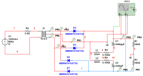
If I increase the leakage in my simulation to 1mH I get ringing. If I add another diode in series (as shown in the schematic below) and keep the leakage as 1mH the ringing decreases.
The reason is the diode capacitance. I did not understand the issue of the diode reverse recovery causing the ringing. The Schottky should have decreased the ring as it has no reverse recovery. It did not in my initial simulations.
My question then was why? It must not be diode reverse recovery.
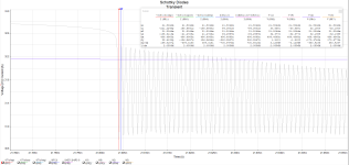
Adding the second diode in series would decrease the dual diode's assembly capacitance. Schottky have a lot more capacitance at the same current rating, so this would create more ringing at a different frequency, as the simulation shows. (See figures attached)
This means that a transformer with a split winding construction would be more problematic as it would have greater leakage L.
I will get a split bobbin transformer to add to the mix.
Please ask if anyone wants to see the initial simulations, and I will post.
So far, I have two transformers and toroids with very low secondary leakage. The range is 34uH to 37uH. I have used this value in simulation and got little to nothing regarding ringing with 1N4006 diodes in a bridge configuration.
If I increase the leakage in my simulation to 1mH I get ringing. If I add another diode in series (as shown in the schematic below) and keep the leakage as 1mH the ringing decreases.
The reason is the diode capacitance. I did not understand the issue of the diode reverse recovery causing the ringing. The Schottky should have decreased the ring as it has no reverse recovery. It did not in my initial simulations.
My question then was why? It must not be diode reverse recovery.
Adding the second diode in series would decrease the dual diode's assembly capacitance. Schottky have a lot more capacitance at the same current rating, so this would create more ringing at a different frequency, as the simulation shows. (See figures attached)
This means that a transformer with a split winding construction would be more problematic as it would have greater leakage L.
I will get a split bobbin transformer to add to the mix.
Please ask if anyone wants to see the initial simulations, and I will post.
Attachments
I didn't see any ringing or "snap off" in your oscillographs..could you annotate please?It is bit more compacted with silicone diodes.
What diode storage time theory and spice shows is the current in a silicone diode does not fall neatly to zero.
In fact the diode current reverses when the transformer voltage falls below the storage capacitor voltage as the diode takes time to shut off when it experiences "reverse current".
Reverse current is required to turn a silicon diode off. The time that takes is the "diode storage time".
The reverse current is required to remove the "carriers" of current in the diode's junction.
This is a finite charge (energy) in the diodes junction that must be removed before the diode will turn off.
This reverse current takes time and energy (diode storage time) and during that time the diode is still turned on and reverse current is flowing in the transformer secondary.
Finally when all the junction current carries are removed the diode snaps off.
It is this last snapping off of the diode while there is significant REVERSE current flowing in the transformer winding that creates the abrupt current change and starts the ringing event.
Note in the attached spice result the transformer secondary voltage is undisturbed after the zero current event and ringing does not happen until the diode is under reverse current snaps off rapidly.
Using multiple series ss diodes, in lieu of just a single ss diode, also has the effect of slowing the transition from on to off, as the voltage change from on to off is twice, and as such reduces the abruptness of the current change.
It's also why, imho, it is better to use a lower current rated ss diode that is still applicable (ie. if the supply is ok with a 1N4007 then there may be a noise disadvantage in using say a 1N4508, and similarly for UF styles, and certainly for bridges like choosing a 35A bridge in the hope that its robustness is the key benefit).
It's also why, imho, it is better to use a lower current rated ss diode that is still applicable (ie. if the supply is ok with a 1N4007 then there may be a noise disadvantage in using say a 1N4508, and similarly for UF styles, and certainly for bridges like choosing a 35A bridge in the hope that its robustness is the key benefit).
In a late 1980s I got access to spice running on a small mainframe.Way back in the early 1970s, the great-grandfather of all simulators, Berkeley SPICE 2G6
At the time I was designing line interfaces for long loops for the telecom industry. Lots of analog to take into account...to much for doing all calculations by hand and getting a useful result in a reasonable time frame. Then there was the worst case tolerance calculations as these were made by the millions. OMG...
With spice on this machine I had a basic text printer that could produce ASCI based graphs of spice sweeps in just hours.
LOL. I thought this was what heaven was going to be like for sure.
I started a little earlier using Berkeley Spice on a VAX (?) to match IR's recently released IRF130 hexFET waveform in a resonant inverter, with the tractor feed printer output extending many meters for a waveform 'plot'. PSpice provided Monte Carlo runs, which gave some confidence to what could be expected for product performance in the real world. Then behavioral modelling came in to allow sims to include parts/systems that didn't yet have a base model.
I bought one of those eighteen dollar oscilloscope kits on eBay, the "DSO138", and tried it out with Quasimodo and some transformers and some inductors. I found it to be a cute little electronic stunt and enjoyable hobby plaything, but not actually useful in combination with Quasimodo.
The thing simply isn't fast enough to digitize and display waveforms from real transformers with real snubbers. Although the claimed bandwidth is 200 kHz and the claimed sample rate is 1 Msps, I couldn't get it to trigger on nonperiodic signals even at much slower settings. It certainly won't display the ringing of a low-leakage-inductance toroidal transformer like the Antek AS-2222, which is used in many chip amps.
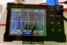
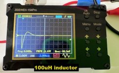
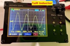
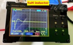
I bought another cheap oscilloscope, the ZEEWEII-154Pro (emphasis on Pro), for about USD 40 on eBay. It's about the size of a business card. Claimed bandwidth is 18 MHz and what's really great is: it is battery powered (USB-C rechargable). It's not connected to the sketchy "ground" of a charger or wall wart.
I tried it on two fixed inductors this morning. I know, they're not quite the same as transformer secondaries, but they're quicker and easier to test when you haven't yet had your morning cup of coffee. They were deliberately chosen to be difficult-for-Quasimodo-and-scope, thanks to abnormally low inductance: 0.1 millihenries and 0.001 millihenries (100uH and 1uH respectively). Take a look at the scope's calculated ringing frequencies: they're HIGH. Which means the scope bandwidth is high and the scope triggering is good. Much much better than the previous device with 0.2 MHz bandwidth.
Those wishing to practice EE calculations can use the displayed ringing frequencies, and the known inductances, to calculate a value of Cx that must have been installed in my Quasimodo. If and when you do, you will discover that Science Works.
If you have an extra forty dollars lying around, and want to make Quasimodo tests, this would be a nice addition to your toolkit. BONUS: you can do the tests in the remote wilderness, 100 miles from the nearest AC mains outlet, if you wish. Just run the Quasimodo PCB from a 9V battery, and run this scope from its internal battery. Cowabunga.
_
Attachments
- Home
- Amplifiers
- Power Supplies
- Simple, no-math transformer snubber using Quasimodo test-jig