So in the other thread (Quasimodo results ONLY) I spotted results for an Antek AS-0515. I have an AS-0518.
The posted values for the Antek AS-0515:
50va dual 15v secondaries
Cx = 0.01uf
Cs = 0.15uf
Rs = 50 ohms and 51 ohms on the other secondary
Could I use the 0515 values, or should they be increased slightly for the 0518?
Thanks!
The posted values for the Antek AS-0515:
50va dual 15v secondaries
Cx = 0.01uf
Cs = 0.15uf
Rs = 50 ohms and 51 ohms on the other secondary
Could I use the 0515 values, or should they be increased slightly for the 0518?
Thanks!
I measured an AS-0518 and got 44.2, so ~50 is probably OK. I will post results in the other forum.
Hi.
If I have primary 230V (shortended) and 2 secondaries with 2 x 30V, do I have to shorten all 3 other secondaries when making the test?
Or is it OK just to shorten the second winding of the tested windings?
Primary: 230V
Secondary 1: 2 x 30V
Secondary 2: 2 x 30V
Thank you in advance.
If I have primary 230V (shortended) and 2 secondaries with 2 x 30V, do I have to shorten all 3 other secondaries when making the test?
Or is it OK just to shorten the second winding of the tested windings?
Primary: 230V
Secondary 1: 2 x 30V
Secondary 2: 2 x 30V
Thank you in advance.
It depends on how you actually plan on using the transformer. Multiple configurations are covered (along with helpful diagrams) in the design brief / instruction manual posted on page one of the thread. You'll find page 11 very useful among all the rest.
I for one have really been having a lot of fun with the Zen Mod Iron Pre. And it occurred to me after installing a really wonderful shunt attenuator, that revealed upper limts of iron gain, might there be a way to get the autoformer to behave in a more linear fashion ? Or use quasimoto to fess out characteristics of trafo gain stage. Seems like it rings at wee higher gain.. Food for thought.
I've dug out my SMD Quasimodo board from my parts box. I've used it numerous times in the past for my low voltage DIY SS amps, to great success I much say. Really easy to use.
This time I would like to snub the large valve amp's HT transformer. According to the circuit diagram the transformer has a single 500V secondary, with a smoothed B+ over 600V.
I've been reading through @Bluesystem post Post in thread 'Simple, no-math transformer snubber using Quasimodo test-jig' https://www.diyaudio.com/community/...-using-quasimodo-test-jig.243100/post-7698263
And I'm wondering if it will be possible to to snub such a high voltage transformer as I would like maintain the 150nF, but I don't think it will be possible based on @Bluesystems posts. Looks like I'll have to buy a couple of 2.2nF SMD caps.
Last edited:
I am not a vacuum tube guy so the following could be spectacularly wrong: Take a look at (these 150nF caps in-stock at DigiKey) and see if any of them meets your needs
Perhaps worthwhile posting a link to the schematic, as that description could be interpreted in a few ways. The working voltage of any snubber cap depends a lot on the secondary winding configuration. As @Bluesystem pointed out, the working current through such a cap increases with capacitance, and deep in a capacitor datasheet you may see rms current limits for a capacitor that could be of concern when some safety margin is included.This time I would like to snub the large valve amp's HT transformer. According to the circuit diagram the transformer has a single 500V secondary, with a smoothed B+ over 600V.
Post #1358 of this thread shows the vector calculus ("complex variables") math that allows you to calculate the power dissipation in the snubber resistor, as a function of AC mains frequency, secondary voltage, snubbing resistance value, and series-capacitor value (150 nF in this case).
The expression for RMS current through the capacitor, as a function of those same four variables [mains frequency, secondary voltage, snubbing resistance, and capacitor value] turns out to be a lot simpler. I invite readers to derive it for themselves; it's three lines of algebra on complex variables. When you do, check whether you feel I got the right answer:
And it goes without saying: If you want to know the AC current thru the capacitor for another set of assumptions (fmains ; Vsecondary ; Csnub ; Rsnub min to max) -- just plug your expression for current into a spreadsheet and schmeer Rsnub from small to big in steps of 10^(1/12) which is an excellent approximation of the EIA Standard "E12" series of values.
The expression for RMS current through the capacitor, as a function of those same four variables [mains frequency, secondary voltage, snubbing resistance, and capacitor value] turns out to be a lot simpler. I invite readers to derive it for themselves; it's three lines of algebra on complex variables. When you do, check whether you feel I got the right answer:
For fmains = 60 C.P.S. ; and Vsecondary = 500Vrms ; and Csnub = 150 nF; and Rsnub ranging from 1.0 ohm to 10 Kohms . . . . the AC current thru the capacitor ranges from 24mA RMS when Rsnub is big, to 28 mA RMS when Rsnub is small.
And it goes without saying: If you want to know the AC current thru the capacitor for another set of assumptions (fmains ; Vsecondary ; Csnub ; Rsnub min to max) -- just plug your expression for current into a spreadsheet and schmeer Rsnub from small to big in steps of 10^(1/12) which is an excellent approximation of the EIA Standard "E12" series of values.
Perhaps worthwhile posting a link to the schematic, as that description could be interpreted in a few ways. The working voltage of any snubber cap depends a lot on the secondary winding configuration. As @Bluesystem pointed out, the working current through such a cap increases with capacitance, and deep in a capacitor datasheet you may see rms current limits for a capacitor that could be of concern when some safety margin is included.
This is the schematic of the PSU. That amp is a Radford TT 100, hybrid SS/valve.
First, the size of a a 600V AC 150nF capacitor is significant. For example the low cost 150nF 600V AC Kemit pat number R76QN31505050J is about 1" long and 3/4" wide. This is pretty big when you need two for a center tapped transformer setup.
Second, a high value snubber capacitor will draw more current at very high voltages and so snubber resistor dissipation will rise. The reactance of a 150nF capacitor at 60Hz is 1/(150e-9 * 2 * 3.14 * 60) = 17.68k
This was the section of @Bluesystems post that drew my interest, dragging forward those electronic lecture from many, many years ago 🙂
Popping in some UK figures for a 150nF cap at 50Hz is 1/(1.5e-7*2*Pi*50) = 21.2k
Like @Bluesystems that would generate a significant constant draw from the secondary side of the HT transformer, and the cap/resistor being about to cope with powers of 12W, do able for a resistor but for a capacitor (my electronic lecture memory has now petered out to a rough path!)
Like @Bluesystems a reduction in the Cs seems appropriate with a 2.2nF for Cs raises the reactance to 1.5M.
Apolgoies if I'm just retracing @Bluesystems post. I've not yet read the whole thread.
G'day Guys,
I have manged to build myself a Quasimodo without any magic smoke escaping.
I am attempting to get my head around where exactly zeta = 1 actually is.
I am testing a pair of custom wound power transformers for a tube preamp project.
230Vac primaries.
230Vac @60mA B+
12.6Vac @ 2A H+
Lets see if I have this right.
All measurments taken with Cx10nF Cs150nF
First up the B+ for transformer
Transformer 1 Rs = 167R
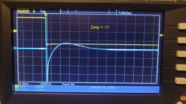
A little bit under-damped due to the almost vertical peak after the trough but not too far off as it settles quickly thereafter.
Transformer 1 Rs = 117R
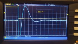
I think this is the point of Zeta = 1 as the ring settles almost immediately.
Transformer 1 Rs= 83R
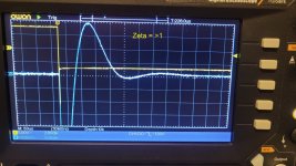
I think here we are over damped as the ringing is getting worse again.
Transformer 1 Rs= 54R
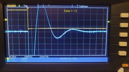
I think here we are at badly over damped.
Did I pass the first test?
I have manged to build myself a Quasimodo without any magic smoke escaping.
I am attempting to get my head around where exactly zeta = 1 actually is.
I am testing a pair of custom wound power transformers for a tube preamp project.
230Vac primaries.
230Vac @60mA B+
12.6Vac @ 2A H+
Lets see if I have this right.
All measurments taken with Cx10nF Cs150nF
First up the B+ for transformer
Transformer 1 Rs = 167R

A little bit under-damped due to the almost vertical peak after the trough but not too far off as it settles quickly thereafter.
Transformer 1 Rs = 117R

I think this is the point of Zeta = 1 as the ring settles almost immediately.
Transformer 1 Rs= 83R

I think here we are over damped as the ringing is getting worse again.
Transformer 1 Rs= 54R

I think here we are at badly over damped.
Did I pass the first test?
Ok, I have re-read the textbook and researched and hopefully understood the nature of the lumpity.
Here we ago again.
Cx = 0.010uF, Cs = 0.15uF. Rs = 883R. Almost damped. Zeta = 0.4 I think
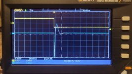
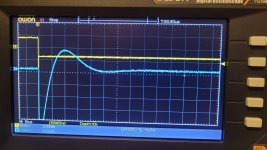
Rs= 654R. 2nd lumpity bumpity juuuuust dissapearing.
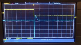
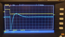
Rs = 553R. 2nd lumpity bumpity gone.
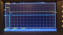
Rs = 465R. Zeta greater than 1
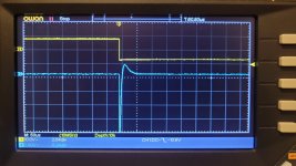
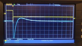
I think I now have my homework correct.
I would think that any 2-3w resistor around the 600R mark would be appropriate.
Did I pass this time?
Here we ago again.
Cx = 0.010uF, Cs = 0.15uF. Rs = 883R. Almost damped. Zeta = 0.4 I think


Rs= 654R. 2nd lumpity bumpity juuuuust dissapearing.


Rs = 553R. 2nd lumpity bumpity gone.

Rs = 465R. Zeta greater than 1


I think I now have my homework correct.
I would think that any 2-3w resistor around the 600R mark would be appropriate.
Did I pass this time?
I myself would choose either 654R by itself, or else a value halfway between 654 and 553, namely 604. Or any EIA standard value within 10-15% of that, which happens to be cheap and easily available from my preferred suppliers.
Please do not forget that the full and complete scientific term is lumpity-bumpity . The oscilloscope wiggles poke up and they also poke down.
Please do not forget that the full and complete scientific term is lumpity-bumpity . The oscilloscope wiggles poke up and they also poke down.
Right.
Now the next homework assignment. Dissipation of Rs.
I have followed the example given here:
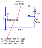
And made this:
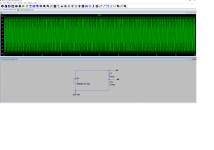
The secondary is 230v. NZ mains is 50Hz.
Measuring point BB
Assuming I have the above right:
20Vpp = 7.07Vrms (according to an internet calculator)
I = E/R
= 7.07/654R
= 0.0108A
P = E x I
= 7.07V x 0.0108A
= 0.076W
Near enough to correct?
Now the next homework assignment. Dissipation of Rs.
I have followed the example given here:

And made this:

The secondary is 230v. NZ mains is 50Hz.
Measuring point BB
Assuming I have the above right:
20Vpp = 7.07Vrms (according to an internet calculator)
I = E/R
= 7.07/654R
= 0.0108A
P = E x I
= 7.07V x 0.0108A
= 0.076W
Near enough to correct?
Yes everything in #2577 is applied correctly and a correct answer has resulted. Congratulations! My own personal preference is to specify resistor wattages at least 3X greater than the anticipated worst-case dissipation in the real equipment. Hey that's just me. So I'd feel good about a 250mW flameproof resistor in that position, and I'd feel even better about a 500mW flameproof resistor. Why flameproof? Because if the gear happens not to be plugged into a surge protector, and a 5000V mains surge comes along, that may apply a super high voltage pulse across the snubbing resistor and we don't want it to set the amplifier on fire. Flameproof resistors are easy to find -- see below -- and easy to buy. Spend an extra twelve pennies on an insurance policy; it's cheap peace of mind.
Attachments
Flameproof it is. I will aim at the vishay PR02 series. 2w, flameproof and not too expensive.
Now for the next challenge. The heater secondary.
This one has stumped me a bit. The secondary seems to require a very low resistance but the magnitude of the oscillation is low when un-damped.
With the same Cx = 0.01uF, Cs = 0.15uF, I get these traces:
Rs = 20R
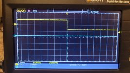
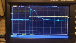
Rs = 16.6R
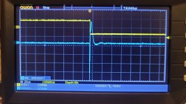
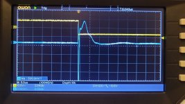
These are the best looking traces that I can get.
Rs=22R
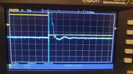
Rs= 39R
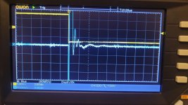
Less than 16R I get oscillation returning.
Higher than 20R and I get excess lumpity-bumpity.
16R-20R seems like a strangely low sweet spot.
But also neither the 20R nor the 16.6R looks quite right.
Should I be increasing the value of Cx/Cs?
Now for the next challenge. The heater secondary.
This one has stumped me a bit. The secondary seems to require a very low resistance but the magnitude of the oscillation is low when un-damped.
With the same Cx = 0.01uF, Cs = 0.15uF, I get these traces:
Rs = 20R


Rs = 16.6R


These are the best looking traces that I can get.
Rs=22R

Rs= 39R

Less than 16R I get oscillation returning.
Higher than 20R and I get excess lumpity-bumpity.
16R-20R seems like a strangely low sweet spot.
But also neither the 20R nor the 16.6R looks quite right.
Should I be increasing the value of Cx/Cs?
Well, another round of testing on the heater secondary.
Cx: 10nF, Cs: 150nF, Rs: infinity.
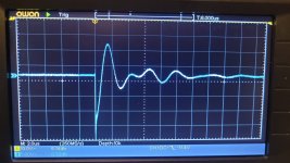
Rs= 228R, starting to dampen
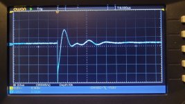
Rs = 18.1R
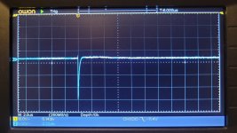
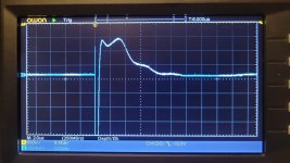
Looks ok a 5V/div but less nice zoomed in.
Rs= 17.4R
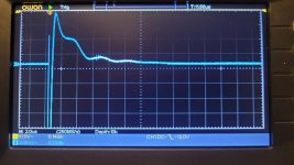
Maybe better but still very wiggly.
At this point, I started trying to increase capacitance.
Cx: 10nF, Cs: 560nF. Rs: 17.4R
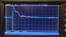
Cx: 10nF, Cs: 1uF. Rs: 17.4R
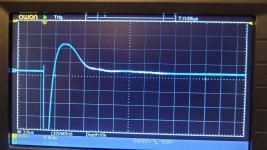
Starting to look better.
Cx: 47nF, Cs: 1uF. Rs: 17.4R
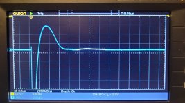
Cx: 47nF, Cs: 1uF. Rs: 20.9R
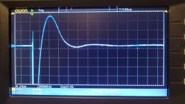
Cx: 68nF, Cs: 1uF. Rs: 20.9R
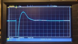
Cx: 68nF, Cs: 1uF. Rs: 17.7R
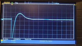
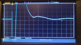
Still a touch wiggly but I think this is good enough.
My working theory is that the heater secondary has high interwinding capacitance requiring much higher Cx to swamp it. Thus requiring much higher Cs.
Am I far off the mark here?
Cx: 10nF, Cs: 150nF, Rs: infinity.

Rs= 228R, starting to dampen

Rs = 18.1R


Looks ok a 5V/div but less nice zoomed in.
Rs= 17.4R

Maybe better but still very wiggly.
At this point, I started trying to increase capacitance.
Cx: 10nF, Cs: 560nF. Rs: 17.4R

Cx: 10nF, Cs: 1uF. Rs: 17.4R

Starting to look better.
Cx: 47nF, Cs: 1uF. Rs: 17.4R

Cx: 47nF, Cs: 1uF. Rs: 20.9R

Cx: 68nF, Cs: 1uF. Rs: 20.9R

Cx: 68nF, Cs: 1uF. Rs: 17.7R


Still a touch wiggly but I think this is good enough.
My working theory is that the heater secondary has high interwinding capacitance requiring much higher Cx to swamp it. Thus requiring much higher Cs.
Am I far off the mark here?
- Home
- Amplifiers
- Power Supplies
- Simple, no-math transformer snubber using Quasimodo test-jig
