Yes and they are not bad as you think. Nigel Pearson in this forum measured it pretty accurately. He showed that they only have some higher distortion than normal at rated power but it is all 2nd harmonic. If you search the forum you might be able to find it. I am referring to the Universal RH, that was the first or one of the first and is the one that has endured.....apparently. There I cannot see any 22K.. Never heard of "looking back" resistors.....
P.Millet has also in his websites amps with Schade fbk. There you can find other measurements too..
P.Millet has also in his websites amps with Schade fbk. There you can find other measurements too..
Last edited:

"I am referring to the Universal RH, that was the first or one of the first and is the one that has endured.....apparently."
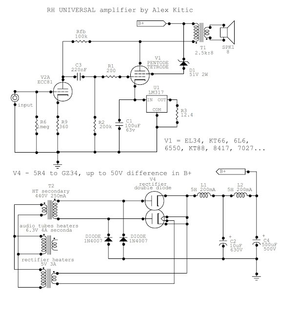
This....
This....
Yes, that's the one. The plate resistor is also the fbk resistor and getting supply thorugh the OPT. Not quite the usual thing.
OK Mr 45, this one is your turn to shew us a solution. 😱Yes, that's the one. The plate resistor is also the fbk resistor and getting supply thorugh the OPT. Not quite the usual thing.
Today there are other items I must cover, time is short, I'm busy & will look in later to see what you come up with.😀
A solution to what? I have never used that circuit. Nigel Pearson built it and measured it and I trust what he did. To me it looks like the 100K resistor is bootstrapped, so the loading conditions for the ECC81 are not what people think and a pentode is not required. It might be actually worse.
Last edited:
The circuit is not the same. Can you spot the difference?V1A should be a pentode.......just like the millet schemes you referred to.
You were simply asked to show us how you would analyze the circuit. And what are its features, benefits & problems are in your opinion.A solution to what?
Why do you lash out, the request seems reasonable.
A simple solution is staring at us, why not have another look, tell us what you think. THX
My opinion I did give it but you ignore it. Read again. And you did not answer to my question FIRST. Not wasting my time, sorry.
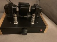
MY solution, I already gave it at post #78. It's REAL thing, not simulations....
MY solution, I already gave it at post #78. It's REAL thing, not simulations....
Attachments
Last edited:
I meant to say, the Universal RH is not the same as Millet's.45 you referenced "The circuit"
I quoted both because AS USUAL Mr. Stewart dismisses/criticizes/bashes everything he doesn't like or understand.
Last edited:
"Bootstrapped" isn't really the right term for this, because it's normally taken to mean positive feedback applied in series, and this is negative feedback applied in parallel. Loading to the driving valve will be 100K in parallel with 100k/gain of about 50, so about 2K Ohm, pretty steep.To me it looks like the 100K resistor is bootstrapped, so the loading conditions for the ECC81 are not what people think
We're seeing this kind of feedback all over lately, but it's not a good choice for triode drivers.
All good fortune,
Chris
OK bootstrap is not the right word, I agree. But there is only one 100K. I can't see it.
Last edited:
ECC81 or pentode?
The plate impedance, rp, of an ECC81 in usual quiescent operating condition is approximately 58k Ohms.
But R9, the un-bypassed 360 cathode resistor of the ECC81 increases rp by (u) x 360 = 36k Ohms.
That makes the ECC81 plate impedance about 58k + 36k = 94k Ohms.
That is starting to come near to the value of some pentodes rp
Some of you already knew that.
But I wrote the above for those who did not know it.
Why does it make a difference?
Because rp = 94k Ohms, has to be compared to the Schade negative feedback resistor, Rfb of 100k Ohms.
And continuing the thought of the ECC81 plate load, there also is the next stage's Rg (R2) of 200k Ohms.
Note: The 100k Rfb is a very difficult load to drive, because the output tube plate signal swing is in opposite phase, versus the ECC81's plate.
Just as Chris Hornbeck said in his Post # 93.
All of this reminds me of Gary Pimm's amplifier that used 6AU6s in Pentode mode to drive 47s, and used Schade negative feedback from the 47 plate to the 6AU6 plate. This was dual Schade negative feedback, the amp was push pull, that required 2 Schade feedback loops, one for push and one for pull.
I tried Schade negative feedback on a single ended amplifier, but I no longer use that method.
Last edited:
You can think about it best in terms of signal current through the "Schade" feedback resistor. At the grid end, there's grid signal voltage, and at the anode end, there's grid signal voltage with polarity inverted times the actual gain of the stage. So the feedback resistor has gain + 1 times grid signal voltage across it - signal current through the resistor is voltage across it divided by its resistance. This current must be supplied by the driving valve, rotating the loadline clockwise.
In this respect, your recommendation of some output valve cathode loading is far superior.
All good fortune,
Chris
In this respect, your recommendation of some output valve cathode loading is far superior.
All good fortune,
Chris
I agree that the loadline rotates clockwise and, as Summer says, the ECC81 with un-bypassed cathode has almost 100K plate resistance. So, it's not like small signal pentode but not far either. However it is more linear, despite it isn't the best representative of the triodes.
I think what matters most is its current. I just don't get how the gain enters this thing (apart from evaluating the anode resistance of the ECC81). I am used to start from the output voltage. I think the total current the ECC81 has to supply in the case of 3.3W with EL84 (which is similar to the ECL86 pentode) is around 2 mA peak max. Its plate resistance sets the amount of signal fed back (and so the total driving voltage) but the load is just set by the actual resistors in the circuit. Now I am curios to try it....
I think what matters most is its current. I just don't get how the gain enters this thing (apart from evaluating the anode resistance of the ECC81). I am used to start from the output voltage. I think the total current the ECC81 has to supply in the case of 3.3W with EL84 (which is similar to the ECL86 pentode) is around 2 mA peak max. Its plate resistance sets the amount of signal fed back (and so the total driving voltage) but the load is just set by the actual resistors in the circuit. Now I am curios to try it....
Last edited:
Okay, let's try another way, because it's not really obvious. Signal voltage appears at both ends of the "Schade" feedback resistor. Total voltage is (gain of output valve + 1) times grid signal voltage. This voltage appears across the Schade feedback resistor and signal current must be supplied on both ends of the resistor. I=E/R. But also, R=E/I, so effective load resistance, the one that matters for signal, is reduced by the same (gain +1) factor.
An extreme example of this is a summing stage, where high gain is used to try to make the input signal voltage try to approach zero and impedance at the summing junction approach zero. (Of course, in this use series resistors are added from each source). Here the summing junction would correspond to our output valve grid, but with a very high gain.
Does that make any better sense?
All good fortune,
Chris
What puzzles me is that the resistance cannot physically change. The gain does. This is how I see it: for example, EL84 SE 3.4Vrms drive, 4.5W out for 5.2K load. That is about 153V rms at the primary. The gain is 45. When the feedback is on, because the anode resistance of the ECC81 is about the same as the fbk resistor and in parallel to 200K, now the gain of the EL84 is about 2.4 and the ECC81 has to provide about 40% of the output voltage + 3.4V to the grid of the EL84. The load is 100K //200K. The clockwise rotation is associated with the fact that the cathode of the ECC81 is not bypassed. It's a relative thing.
The current swing of the ECC81 is less than 1.4 mA peak into 67K which is more than usual but also well within its possibilities if biased with enough anode current. The un-bypassed cathode will increase the anode resistance but it's also making it more linear?
The current swing of the ECC81 is less than 1.4 mA peak into 67K which is more than usual but also well within its possibilities if biased with enough anode current. The un-bypassed cathode will increase the anode resistance but it's also making it more linear?
Last edited:
- Home
- Amplifiers
- Tubes / Valves
- Simple ECL86 amp