So you salvaged the ECL86's from two HMV Model 2202 taperecorders? In a thread earlier this month you posted the schematic of the HMV 2202. The tubes in it are ECC83, ECL82 and EM84.
I haven't salvaged anything, Columbo. I'm leaving the tape recorders complete. They're not HMV 2202's as I first presumed. They where not yet in my possession when I made that assumption.So you salvaged the ECL86's from two HMV Model 2202 taperecorders? In a thread earlier this month you posted the schematic of the HMV 2202. The tubes in it are ECC83, ECL82 and EM84.
Hope that's ok with you ☺️
To be honest, I'd quite like to see at least 1 working as a tape player. They both came with tapes and Imy interested to hear what's on them. Probably nothing interesting but it's a piece of history non the less.
Thanks for the compliment!I haven't salvaged anything, Columbo.
From your post #1 of this thread:
"I posted another thread on here relating to a similar project salvaging parts from an (sadly broken) old tape recorder. However, it turns out I have different valves than I originally though and so, I have started a fresh with a new thread."
So is it so strange that I thought that you did salvage something?
But don't bother to reply. I'll stay out of this thread from now anyway.
Hi Peacocksuit,
Those tapre recorders probably have a very basic circuit, and probably just need a couple of PSU caps and a coupling cap or two to fix. It could be a good exercise to do a minimal renovation. If you can get them to work as simple PAs (a lot of taperecorders have that feature) then you could have a simple tube practice amp for a guitar enthusiast. Then you should have no difficulty moving them on.
As mentioned, I had fixed a couple of old tape recorders before, and they were surprisingly good as a bluetooth player, propped up on a shelf in front of where I work. It was quite rewarding hearing what a difference a sympathetic renovation had on the sound.
Cheers, Richard
No offense meant, just a bit of humour.
Sorry if it didn't come across that way
OK. And sorry for my somewhat dramatic reaction. I was probably in a bad mood...
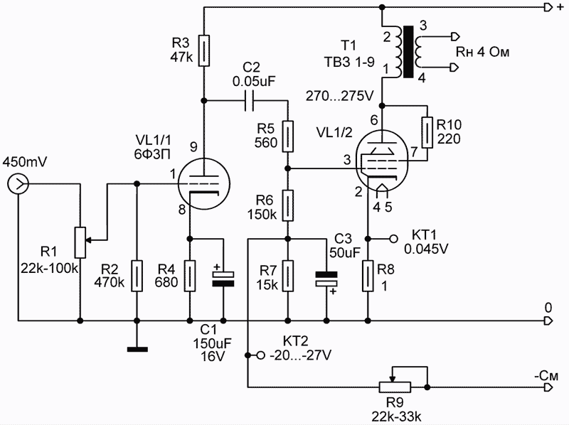
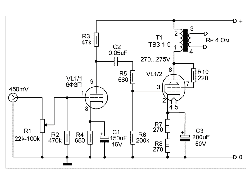
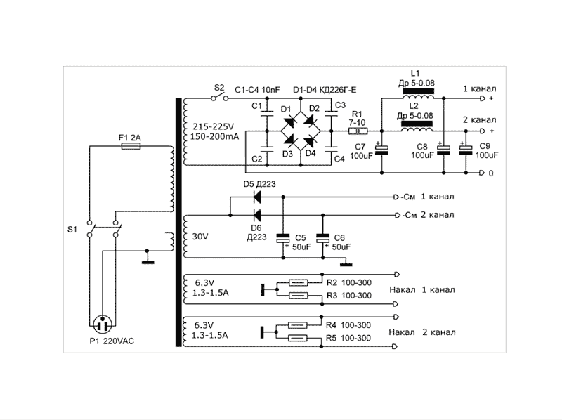
A distinctive feature of this lamp amplifier is simply the absence of scarce parts, but at the same time it has a good sound. Due to the ease of setup and high repeatability, this amplifier can be recommended to beginner radio amateurs. The author of this scheme is Anatoly Manakov. The output power of the amplifier is 2.5 W with a coefficient of non-linear distortion of 0.5-1%. The frequency range of the amplifier is from 30 Hz to 20-23 kHz. The amplifier is made according to a two-stage scheme. In each channel of the amplifier it is used on one 6F3P lamp. The 6F3P lamp is combined, it contains two lamps, a triode and a beam tetrode in one cylinder. The 6F3P triode lamp is used for preliminary signal perception, and the tetrode operates in the sensing output stage. The input signal through the consumption regulator consumes the grid of the 6F3P triode, wins and consumes from the anode through the isolation capacitor to the control grid of the output stage. The output stage is made according to a triode circuit, in which the screen grid of the 6F3P tetrode is connected to the anode through a resistor with a resistance of 220 ohms. In contrast to the tetrode mode, in the triode mode, its resistance is reduced several times, and a more linear characteristic of the lamp is applied. The disadvantage is the higher power output. The output stage on the 6F3P tetrode is loaded onto the TVZ-1-9 output transformer from a tube TV. Other output transformers of the TVZ series from tube TVs can also be used in the amplifier. Excellent results can be obtained with Edcor transformers. It is proposed to repeat the circuit of two amplifiers at 6F3P, the first (Fig. 1) - with the installed one, the second (Fig. 2) - with automatic bias of the output stage, a little constructively. Figure 3 shows the power supply circuit of the amplifier.


Рис.1. Схема лампового усилителя на 6Ф3П с фиксированным

Рис.2. Схема лампового усилителя на 6Ф3П с автоматическим смещением

Рис.3. Схема блока питания лампового усилителя на 6Ф3П
Детали . В усилителе применяются резисторы резистора МЛТ-0,5, разделительный конденсатор С2 типа К71-7, можно применять конденсаторы К78, К73. Блок питания выполнен на силовом трансформаторе от магнитофона «Комета-201». Можно применить унифицированные трансформаторы ТАН-28 , ТАН-29 , в крайнем случае при соединении усилителя с автосмещением можно применить силовой трансформатор ТС-180 от чёрно-белого ТВ, хотя он велик для этой конструкции. Дроссели Др5-0,08 от цветных ламповых телевизоров УЛПЦТ, или применение стандартных унифицированных дросселей Д22 , Д31 .
Электролитические конденсаторы в анодном питании К50-32 100мкФх350В, можно применять конденсаторы других типов на такое же напряжение, или выше-400В. Вместо дросселя можно применить резисторы МЛТ-2 номиналом 250-300 Ом, но ёмкость электролитических конденсаторов в этом случае желательно увеличить вдвое. Электролитические конденсаторы в выпрямителе с напряжением 50-100В.
При работе усилителя на загрузку 8 можно применить выходные трансформаторы ТВЗ-1-1, ТВЗ-1-2, ТВ-2АШ, ТВ-1-Л-1 от чёрно-белых телевизоров. При работе на нагрузку 4 Ом можно применить выходные трансформаторы ТВ-2Ш2, ТВЗ-1-9 от чёрно-белых и цветных ламповых телевизоров. При работе на нагрузке 16 Ом можно применить трансформаторы кадровой развертки ТВК, но при этом АЧХ усилитель может сузиться до 15-17 кГц.
настройка усилителя. При исправной лампе и правильном монтаже первый каскад в настройке не нуждается. настройка второго каскада сводиться к регулировке тока тока тетрода лампы 6Ф3П в пределах 40-45 мА по контролю производительности в катоде. При этом падение напряжения на катодном резисторе номиналом в 1 Ом должно быть в пределах 0,04-0,045 В постоянное напряжение. Для выбора усилителя с автоматическим смещением требуется подборка катодных резисторов так, чтобы ток через лампу на выходе схемы был мощностью 40-45 мА, при этом падение напряжения на этих резисторах будет в пределах 20-24 В.

Рис.1. Схема лампового усилителя на 6Ф3П с фиксированным

Рис.2. Схема лампового усилителя на 6Ф3П с автоматическим смещением

Рис.3. Схема блока питания лампового усилителя на 6Ф3П
Детали . В усилителе применяются резисторы резистора МЛТ-0,5, разделительный конденсатор С2 типа К71-7, можно применять конденсаторы К78, К73. Блок питания выполнен на силовом трансформаторе от магнитофона «Комета-201». Можно применить унифицированные трансформаторы ТАН-28 , ТАН-29 , в крайнем случае при соединении усилителя с автосмещением можно применить силовой трансформатор ТС-180 от чёрно-белого ТВ, хотя он велик для этой конструкции. Дроссели Др5-0,08 от цветных ламповых телевизоров УЛПЦТ, или применение стандартных унифицированных дросселей Д22 , Д31 .
Электролитические конденсаторы в анодном питании К50-32 100мкФх350В, можно применять конденсаторы других типов на такое же напряжение, или выше-400В. Вместо дросселя можно применить резисторы МЛТ-2 номиналом 250-300 Ом, но ёмкость электролитических конденсаторов в этом случае желательно увеличить вдвое. Электролитические конденсаторы в выпрямителе с напряжением 50-100В.
При работе усилителя на загрузку 8 можно применить выходные трансформаторы ТВЗ-1-1, ТВЗ-1-2, ТВ-2АШ, ТВ-1-Л-1 от чёрно-белых телевизоров. При работе на нагрузку 4 Ом можно применить выходные трансформаторы ТВ-2Ш2, ТВЗ-1-9 от чёрно-белых и цветных ламповых телевизоров. При работе на нагрузке 16 Ом можно применить трансформаторы кадровой развертки ТВК, но при этом АЧХ усилитель может сузиться до 15-17 кГц.
настройка усилителя. При исправной лампе и правильном монтаже первый каскад в настройке не нуждается. настройка второго каскада сводиться к регулировке тока тока тетрода лампы 6Ф3П в пределах 40-45 мА по контролю производительности в катоде. При этом падение напряжения на катодном резисторе номиналом в 1 Ом должно быть в пределах 0,04-0,045 В постоянное напряжение. Для выбора усилителя с автоматическим смещением требуется подборка катодных резисторов так, чтобы ток через лампу на выходе схемы был мощностью 40-45 мА, при этом падение напряжения на этих резисторах будет в пределах 20-24 В.
Last edited by a moderator:
Details . The amplifier applies resistors of the MLT-0.5 resistor, the C7-type separator capacitor, C71-7, can be used Capacitor K78, K73. The power supply is made on the power transformer from the Comet-201 tape recorder. You can apply unified TAN-28 transformers, TAN-29, as a last resort, when connecting an amplifier with automotive, you can apply the power transformer TS-180 from the black and white TV, although it is great for this design. DR5-0.08 chokes from Color tube TVs ULPCT, or the use of standard unified chokes D22, D31.
Electrolytic capacitors in anodic power supply K50-32 100MKFH3B, you can use condensers of other types to the same voltage, or above-400V. Instead of throttle, you can apply resistors MLT-2 with a face value of 250-300 ohms, but the capacity of electrolytic capacitors in this case is desirable to increase twice. Electrolytic capacitors in a straightener with a voltage of 50-100V.
When the amplifier is working on loading 8, you can apply TWZ-1-1 transformers, TVZ-1-2, TV-2Ans, TV-1-L-1 from black and white TVs. When operating on the load of 4 ohms, you can apply the TV-2S2S2, TWZ-1-9 from black and white and color tube TVs. When working on a load of 16 ohms, you can apply transformers of frame sweep of TCEs, but at the same time the ACH amplifier can narrow to 15-17 kHz.
Adjust the amplifier. With a good lamp and the correct installation, the first cascade in the setup does not need. Setting the second cascade to adjust the current current Tetrode lamps 6F3P in the range of 40-45 mA to control the performance in the cathode. At the same time, the voltage drop at the cathode resistor with a par value of 1 ohms should be within 0.04-0.045 per constant voltage. To select an amplifier with an automatic displacement, a selection of cathode resistors is required so that the current through the lamp at the output of the circuit is 40-45 mA, while the voltage drop on these resistors will be within 20-24 V.
English please.
dave

diyAudio moderation team
Note: there seems to be some sort of auto-translate system, shown up since the new BBS sw, that is putting original language posts inso take extr care.
English please6F3P - ESL82, 6F5P-86
It sounds perfect, 5k output transformer
Yet:
For an amp like the one posted, the 0.22 coupling caps are far too large for any benefit.
I'd use 0.047's instead, they'd be better for taming down any postive grid voltage problems, and still provide plenty of bass.
I'd use 0.047's instead, they'd be better for taming down any postive grid voltage problems, and still provide plenty of bass.
Hello everyone, I would like to back to initial post in this thread, published at 2022-01-23 by Peacocksuit. He reffered video where one guy from YouTube channel who inplemented ECL82 in very interesting way with series of local feedback not a global one. I am wondering can I substitute DIRECTLY ECL82 to ECL86? Directly I mean WITHOUT CHANGING RESISTORS VALUES ETC. Just electrical values (please ignore pinout and heaters supply voltage) - just anode/kathode current etc.?
As referance see the schematic I have copied from the movie on YouTube (
)

As referance see the schematic I have copied from the movie on YouTube (
Thank you - could you please elaborate more on topic?That looks like Schade feedback. Plate-to-Plate. Typifies in modern times by the RH84.
dave
I am wondering can I substitute DIRECTLY ECL82 to ECL86?
I read that both sections - triode and pentode - are different.
"None of the ECL 80/82/83/86 have compatible pin-outs. Perhaps just as well because their characteristics are quite different."
Just to be complete, clear up any misunderstandings, and maybe be a little helpful if I can...Is the resistor "180 R" supposed to be 180K or is it just 180 ohms?
When you see R, k, or M with resistor values, they mean:
R = ohms --- for instance, 10R = 10 ohms
k = kilohms (ohms * 1000) --- for instance, 10k = 10,000 ohms or 10 kilohms
M = megohms (ohms * 1,000,000) --- for instance 10M = 10,000,000 ohms or 10 megohms
small 'm' is confusing, and is not typically used for stating a resistance value in ohms. Technically speaking, it would mean a thousandth of an ohm (1m = 0.001 ohm), but there might be some argument over that -- which illustrates why you won't see people using it! Besides, we don't usually need to use devices with resistance of a few thousandths of an ohm.
To add to the fun, Europeans and Americans use different shorthand formats for stating passive device values. Europeans put the R, k, or M (or u, m, n) in the middle of the numerical value, in place of the decimal point used by Americans. Like this:
2R7 = 2.7R = 2.7 ohms
2k7 = 2.7k = 2700 ohms
2M7 = 2.7M = 2,700,000 ohms
for capacitors:
2p2 = 2.2pF = 2.2 picofarads
2n2 = 2.2nF = 2.2 nanofarads (= 2200pF)
2u2 = 2.2uF = 2.2 microfarads
I don't want to think about inductors... I'd much rather see 1.5mH than "1m5 H".
Another factor for the 'European' way might be the thousands separator and decimal point. Most Europeans write 100.100,1, but Brits and US would write 100,100.1, so 2R7 is unambiguous.
- Home
- Amplifiers
- Tubes / Valves
- Simple ECL86 amp